Machine-vision systems exploit uniform illumination to reduce inspection errors
Machine-vision systems exploit uniform illumination to reduce inspection errors
By Lawrence H. Brown, Contributing Editor
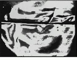
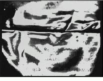
During the past several years, off-the-shelf illumination systems have allowed specular parts and surfaces, such as surgical instruments or knurled foil on pharmaceutical packaging, to be examined by machine-vision systems. Reflected glare from such shiny surfaces produces dark, shadowy effects when fluorescent or fiberoptic ring lights are used (see Fig. 1). This problem is further complicated by the viewing aperture of the imaging system. Such apertures interrupt the light`s reflection to the camera system, leaving a shadow or black hole at the central area of the part being inspected (see "Uniform lighting increases image quality," p. 22).
Companies requiring the inspection of specular parts were left with only partial solutions, none of which were reliable. Methods such as light tents that use makeshift housing to reflect light or inspection of parts by hand were the only means companies had to inspect such parts. Currently, problems such as finding cracks in silicon wafers or inspecting the integrity of ball-grid arrays have spurred industry efforts to improve the reliability of advanced illumination techniques.
Concept shift
Tim White, founder and principal scientist for Northeast Robotics (Weare, NH), began to experiment with the concept of developing uniform light sources. After several investigations, he eventually was able to design off-the-shelf uniform illumination systems for parts inspection.
Rather than analyzing illumination from the perspective of a vision engineer, White analyzed the illumination field from the object`s point of view. In this approach, he analyzed the object`s specific geometric properties. Making this change in perspective means viewing the inspected part as an object in space, in the context of its illumination field with azimuth and elevation, rather than merely considering the object as lying on a flat surface with x and y plotted coordinates. "We don`t sell lighting illumination," says White, "we sell geometry. And the geometry and technical aspects of illumination are not taught at engineering schools."
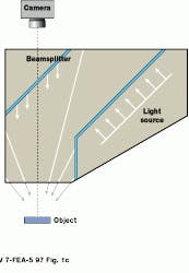
The important principles of producing a uniform light source are creating large solid angles of light through beamsplitting, using and directing two or more uniform light sources, and fabricating a housing that directs the light`s reflection for a uniform illumination field (Fig. 1c).
Compact-disk inspection
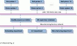
At Autoroll Machine Co. (Middleton, MA), where nearly 50% of the country`s compact disks (CDs) are manufactured, Alexander Kolchinsky, founder and president of Automation Visual Inspection Systems (AVIS; Middleton, MA), has integrated Northeast Robotics` illumination systems into a custom machine-vision inspection system. He has integrated an automated screen roll printer and an inspection station. This station can operate either as a stand-alone system or as part of a local-area network (LAN), linking as many as 16 stations to a quality-assurance database and manufacturing network (see Fig. 2 on p. 24). Each station can print and inspect 75 compact disks per minute with close to 100% accuracy throughout the process.
The machine-vision inspection system performs three separate operations per minute. First, using a ring light, it makes an identification check for the CD`s barcode and catalog number. Second, using a continuous field of illumination, the system inspects the colors after print ing. Third, the CD is inspected for defects.
To build each inspection station, Automation Visual Inspection Systems chose a Windows-based Pentium 100 industrial, single-board computer with a 14-slot chassis.The company integrated PC-based image-processing boards and OEM software from Sharp Digital Information Products (Huntington Beach, CA) to perform inspection operations and to manipulate data.
Kolchinsky chose the GPB-2 board from Sharp to gain additional flexibility in structuring his proprietary algorithms. In particular, he discovered that Sharp`s subroutines from its C-based library allows the detection of smaller defects without having to change the equipment or the illumination. Auxiliary boards from Sharp have been added to obtain faster alignment and better warp and rotation of the inspection process. A proprietary board was used for the lighting and program mable logic controller interface.
In operation, a halogen-based lighting system from Fostec (Auburn, NY), which is workstation-controlled, guides light through fiberoptic cables into Northeast Robotics` light box. The light is converged through eight different points to place the lighting over a specific area to achieve uniform illuminaton. Several Sony XC75 CCD cameras from Industrial Vision (Carrollton, TX) capture the images for inspection; either black-and-white or color cameras can be used, as required.
With machine-vision systems becoming less expensive, the cost savings of production manufacturing might be directed to the illumination subsystem for inspecting parts. In manufacturing products where uniform illumination has had the largest impact, such as for electronic and semiconductor devices, illumination improvements have proved cost-effective. "Performance has improved tenfold," says John Merva, Northeast Robotics` general manager, "because improving the illumination removes the artifacts from the image. That increases the repeatability of the system."
Addressing both the industrial demands of solving production inspection problems and the results achieved by a more analytical approach for illuminating machine-vision systems should spur additional studies and advancements.
FIGURE 1. Comparison of images obtained from a printed foil package shows how continuous illumination makes parts inspection easier using a two-inch fluorescent ring light for illumination and the patented Square Continuous Diffuse Illuminator (SCDI) from Northeast Robotics. In the SCDI device (right), light rays reflect off a beamsplitter and the lower chamber of its housing, thereby increasing the solid angle of illumination. The light source is tilted parallel to the beamsplitter to obtain greater uniformity.
Uniform lighting increases image quality
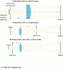
Maintaining uniform and continuous illumination of parts under inspection is a common problem in machine-vision systems. While uniform lighting often simplifies image processing and does highlight parts` edges or material transitions, image quality can still vary across the field of view depending on what lens subsystem is being used. Consequently, the use of uniform lighting could result in images that appear brighter in their center than at their periphery. Although using larger-format enlarging lenses minimizes this vignetting, such as in applications where the signal-to-noise ratio is at a premium, this level of correction would not be sufficient. When light uniformity across the image field of view is critical, telecentric lens subsystems can be used to solve this problem.
Adding an aperture positioned one focal length in front of the existing imaging lens ensures light uniformity across the field of the image. Systems also can be built in which the aperture is one focal length behind the lens and the lens is one focal length from the part. In this setup, the telecentric lens creates a constant, parallel perspective view with uniform light collection across the part under inspection. With the addition of field- and reimaging optics, this type of lens provides a constant magnification at all part positions with no parallax error, but with the limitation that the lens must be bigger than the part.
In those applications where viewing a part bigger than the lens and farther away than one focal length is required, the use of an aperture in front of the imaging lens is beneficial in capturing uniform images of uniformly lighted parts.
Kevin Harding
Industrial Technology Institute
POB 1485
Ann Arbor, MI 48106
E-mail: [email protected]
Proper positioning of the aperture, telecentric lens, and part under inspection in a machine-vision inspection system can result in uniform and continuous part illumination as well as quality images.
FIGURE 2. At Autoroll Machine Co., a 100-kbit/s local-area network links 16 vision systems to a quality-assurance station and to a manufacturing/factory network made up of scheduling, art, and manufacturing departments. Each vision system also performs self-tests, so that, for example, the maintenance department can determine when to replace a lamp.
