Inspecting abrasive surfaces for defects
Modified web-inspection system checks sandpaper for lack of pattern uniformity.
By C. G. Masi, Contributing Editor
Machine-vision systems typically seek to identify a distinctive pattern in an image, then measure dimensions or other properties from that image that it can compare to a standard to make a decision, such as whether to accept or reject a part. In some cases, however, the system is not looking for a pattern. Rather, it is looking for a lack of pattern.
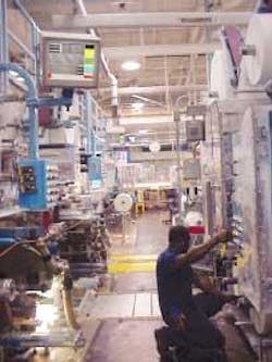
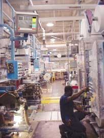
A manufacturer of abrasive products, such as sandpaper, approached AccuSentry to help solve this problem. “What they’re really looking for is a very uniform noisy environment,” says J. J. Roberts, vice president of AccuSentry, about the inspection problem presented by the abrasives manufacturer. AccuSentry’s business includes building standard inspection products, as well as creating custom solutions. To solve the abrasives-manufacturer’s web-inspection problem, the company started with its standard Sentry 9000 web-inspection system and extensively modified it to fit the application (see photo).
“If you are using sandpaper with grit particles that are supposed to be spaced 1/16 of an inch apart,” Roberts points out, “and all of a sudden you have an area where they’re 1/30 of an inch apart, it would cause a streak in your end product-whatever you’re sanding. The particles need a very uniform randomness to create a nice abrasive material.”
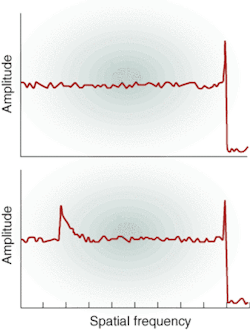
Uniform randomness looks like white noise in an image’s spatial-frequency spectrum (see Fig. 1). That is, the signal amplitude is pretty much uniform over most of the spatial-frequency range. In the case of an abrasive, however, the pattern is made up of uniformly sized specks, which causes a sharp peak at the spectrum’s high-frequency end. The spectrum cuts off at that point, because the specks are usually the smallest things in the image.
A clump, on the other hand, shows up as another peak at the spatial frequency corresponding to its size. Wider clumps show up at lower spatial frequencies than narrower clumps. A clump also adds to the amplitude at higher spatial frequencies, since it is made up of more specks thrown closer together. Voids, too, leave characteristic signatures in the spatial frequency spectrum.
Line INSPECTION
The abrasives manufacturer wanted an automated inspection system for a wide range of products made by bonding abrasive particles to paper or cloth backing. The products range from coarse grades made with particles nearly a millimeter across spread widely apart (a few particles per square centimeter) to extremely fine grades made with microscopic particles placed so close they touch. Papers can be any color and can be so thin that writing on the back shows through. The most common defects are voids (patches with especially few particles), clumps (regions with too many particles), and creases (which show up as linear wrinkles). In addition, there are sometimes discolorations, tears, holes, or other defects.
The production system uses a web 66 in. (168 cm) wide that runs continuously at up to 350 ft/min (1.8 m/s). Roberts’ team had to come up with an inspection system that could be installed on an existing production line.
The team devised a system that uses two types of lighting simultaneously: uniform overhead light and structured light. Overhead light shows up coloration, clumps, and voids, while structured light brings out the wrinkles. The overhead light comes from a set of AccuSentry 6-ft (183-cm) T8 lamp assemblies (ASI 9000-FLUOR 72 ASSY) operating at 25 kHz. The structured light comes from six Illumination Technology 4900 ET illuminator halogen light sources, controlled remotely via Ethernet. An Illumination Technology 4910 SmartCal calibrating device balances the sources.
Balancing the illumination between overhead and structured light is important. Too much overhead light, for example, can wash out the shadows that structured light produces. Too little, however, can leave the system unable to distinguish voids and clumps. “They’ve got to be very balanced,” says Brian Riddle, machine-vision applications engineering manager at AccuSentry.
“We take a focusing template and put it under the cameras to balance the lighting using an automatic exposure routine that also sets each of the cameras [for equal sensitivity]. If the exposure times are significantly different, the system adjusts the aperture of the deviant camera and repeats the autoexposure until all the camera exposure times are reasonably equal,” Riddle says.
The focusing routine balances the overhead- and structured-light levels by adjusting the structured-light lamp intensity. The halogen lamp source for structured light is an incandescent source energized by an adjustable power supply. The Sentry 9000’s built-in host computer controls the power supply’s output via Ethernet.
Lenses and reflectors in the structured-light head focus light from the halogen lamp onto a fiberoptic bundle. The fibers carry the light to an enclosure mounted over the web, which carries the fluorescent tubes and the cameras. There, the bundle fans out to provide a line of directed illumination that shines onto the web surface at an angle. This sheet of structured light provides shadows that highlight any large-scale (larger than the abrasive grains) morphological features, such as creases or tears.
The engineers had to mount the camera and lights in an enclosure to protect them from airborne dust. “Small grit floats in the air and especially close to the production machines,” Riddle recalls. “So we had to take special precaution to enclose the halogen light sources to keep out this dust.”
Halogen lights generate a great deal of heat, so Riddle’s team designed an air-conditioning system into the enclosure. Future versions of the system will have the halogen lamp housing separated from the enclosure. The incandescent lamp has a short service life relative to the fluorescent tubes and other components in the enclosure. It is, therefore, a relatively high-maintenance item that needs to be changed regularly. The abrasives manufacturer, however, wanted to avoid having technicians moving in close proximity to the web to change the bulb. “They’ve got light curtains [around the inspection station] that they don’t want technicians passing through,” Riddle explains. “It would trigger an alarm that stops the web, so they wanted to have the lamp housing outside the curtains.”
PIXEL-LEVEL CONTROL
Clumps and voids are necessarily larger than the abrasive particle size. These defects appear at low spatial frequencies, while the grit texture appears at significantly higher frequencies. When thought of in this way, an obvious approach to image processing is to separate the defects from the texture through spatial filtering, which requires combining information from multiple adjoining pixels.
AccuSentry gets pixel-level control of the image by building its own cameras. It starts with an Eastman Kodak KI 1020 CCD with 1000 × 1000 pixels. “The CCD was originally used for astronomy, and we picked it because it has some unique capabilities,” Roberts points out. Particularly, it is capable of addressing pixels line by line and binning pixels together. “You have 1000 pixels across,” Roberts explains. “We can tell it to absorb light from four pixels at a time. It can absorb the light from adjoining pixels and then distribute it among them. Normally, you’d have a 7.5-μm pixel at the CCD. By binning them together we end up with 15 μm. If you bin it in the machine direction, you get 15 × 15 μm, thereby quadrupling the light collection for the same exposure time.”
As with most web-inspection applications, the usual method is to use a linescan camera. The line length in pixels defines the system’s horizontal (perpendicular to the web motion) resolution, while the refresh rate combined with the web speed defines the vertical (parallel to the web motion) resolution. AccuSentry has found, however, that acquiring 200 lines at a time with its area-scan camera works better.
By simultaneously acquiring 200 image lines at a time, the system collects image information much faster. It also makes decoding structured-light shadows into height information more straightforward. Finally, it allows the image pickup to see the entire illumination stripe, not just a thin line of it, simplifying the camera set up procedure
“There can be multiple cameras across the length of the web, depending on the web width and what kind of resolution defect the customer is interested in,” says Riddle. “The smaller the defect the production engineers are interested in, the more cameras you would require. “As material goes by, we synchronize via an encoder installed on the web to capture every linear inch of it with a small amount of overlap to ensure that we’re not missing any material.”
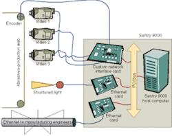
The basic Sentry 9000 system is augmented with PCI bus interface cards capable of controlling and accepting images from up to five cameras (see Fig. 2). The interface card also accepts the encoder signals that synchronize the system with the web. An Ethernet card controls the structured light brightness. A second network card provides secure communications with the abrasive manufacturer’s engineering staff so that they can monitor the production process and the inspection system’s health or control it remotely from anywhere in the world. The operator’s human/machine interface (HMI) works through a touch screen mounted on the Sentry 9000 enclosure. The HMI/inspection software for the Sentry 9000 is a drag-and-drop tool environment written in C++ by AccuSentry.
The system provides a map of the complete web, annotated with color-coded locations for every defect the system finds (see Fig. 3). While the product is manufactured on a continuous web, it is later cut up into much smaller sheets.
With complete and accurate information on exactly where each defect is in each roll that comes off the web, the manufacturer can maximize the yield of good product by judiciously cutting it into sheets. The manufacturer can discard sheets where the defects fall and can even selectively plan to cut up sheets to avoid the defects.
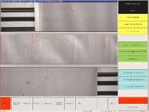
While the defect map is indispensable for downstream processing, the system provides more immediate feedback to operators as well (see Fig. 4). “We’ve got a live update on the screen to give the operator a live feedback of the image as it’s being taken,” says Riddle. “We provide the option of displaying only the defect. The user can turn that mode on and the HMI will only display the defects instead of spending time updating with pictures of good material. It will update only when a defect comes along, then hold it until the next defect.”
Operators can also save those defect images to permanent memory. Then, by double-clicking a spot on the defect map, they can recall the stored image for review. Saving images also allows engineers to reprocess them on their desktop workstation and optimize production parameters at their leisure, instead of in the production environment.
Company Info
AccuSentry, Marietta, GA, USA www.accusentry.com
Eastman Kodak, Rochester, NY, USA www.kodak.com
Illumination Technology,Syracuse, NY, USA www.illuminationtech.com
