Machine vision speeds automated PCB inspection
In the manufacture of surface-mount print ed-circuit boards (PCBs), the presence, position, and orientation of surface-mount components must all be checked before soldering can occur. Although once accomplished manually, today’s automated PCB production lines mandate the use of fully automated, high-throughput inspection systems.
To meet these demands, developers of PCB inspection systems offer Surface Mount Equipment Manufacturers Association (SMEMA) compatible equipment that can be interfaced with pick-and-place, reflow soldering systems and other automated equipment used in the manufacture of surface-mounted PCBs. “By conforming to this standard,” says Alan Hagler, an automation engineer with Design and Assembly Concepts (DAC; Leander, TX, USA; www.dac-us.com), “single-board transfer systems designed for PCB inspection can be integrated with other conveyor transports without any interface hardware.”
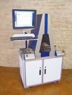
At this year’s NIWeek (Austin, TX, USA), DAC introduced its latest SMEMA-compatible PCB inspection system, the Roadrunner X4. “Because the machine needs to be customized to meet the needs of many different PCBs,” says Hagler, “it was important to build the system with a flexible user interface so that a number of different inspection tasks could be tailored for each individual customer.” To accomplish this, Hagler and his colleagues used LabVIEW from National Instruments (Austin, TX, USA; www.ni.com) to develop a GUI that controls both machine vision and motion tasks.
Populated PCBs move from a SMEMA-compatible placement machine to the Roadrunner X4. Here, component position, orientation, and presence must be inspected as well as the presence, location, and amount of solder paste. As each 16.5-in.-wide board moves into the system, it is detected by an IR detector from Banner Engineering (Minneapolis, MN, USA; www.bannerengineering.com), which is used to initiate the motion of a conveyor. To control the motion of this conveyor, a PCI-based 73XX motor controller from NI was coupled to a stepper motor amplifier from Parker Hannifin - Compumotor (Rohnert Park, CA, USA; www.compumotor.comstepper), which in turn drives a stepper motor from Oriental Motor (Torrance, CA, USA; www.orientalmotor.com).
“One of the challenges of designing such conveyor-based system,” says Hagler, “is that the motion of the conveyor cannot be allowed to rotate the position of the PCB as it moves under the field of view (FOV) of the camera. “By running one track of the conveyor slightly faster than the other,” says Hagler, “we essentially pin the side of the board to one track, fixing the motion of the conveyor as it moves through the system.” In such systems, he says, this is a far easier method than using feedback-encoder mechanisms.
To illuminate each board correctly as it moves under the FOV of a linescan camera, DAC engineers required a 14.5-in. LED line light. Because no such product was commercially available, Hagler and his colleagues developed their own using off-the-shelf LEDs with an 8° illuminating angle and 12-mK luminance. “Mounting 72 LEDs along a 14.5-in.-long line provided sufficient illumination to capture high-contrast images,” says Hagler. Under control of an NI 1424 digital I/O board and a relay, the lighting could be switched on as each board moves through the system.
To digitize images at high enough resolution, a 401k linescan camera from Basler (Ahrensburg, Germany; www.baslerweb.com) was used to digitize images across a 12-in. FOV of each board. Attached to a NI PCI-1428 frame grabber board, linescan images are captured as each board moves through the system resulting in images of 12 k × 4k resolution. Using NI IMAQ machine-vision software, these images are processed on the host PC to check for specific fiducials on the board. Once located, machine-vision routines locate regions of interest within each image to check for presence, position, and orientation of specific parts. At the same time, each image is subsampled and displayed to the operator within the GUI.
“By using a combination of IMAQ machine-vision software and NI motion-control software,” says Hagler, “it was possible to develop a combined motion/vision control system that used a single GUI. Using this user interface, we can rapidly customize the Roadrunner X4 system to meet the demands of a variety of PCB inspection requirements,” he adds. Such concepts have also been integrated into a number of the company’s other products.

