Vision system masters circuit-assembly soldering
Integrated cameras, controllers, and soldering system speed assembly of printed-wire boards.
By C. G. Masi, Contributing Editor
When a large manufacturer of electronics assemblies decided it had enough of hand-soldered final assembly of its switching power-supply modules, they turned to Spectra Technologies (ST), a developer of robotic assembly stations. The problem was unusual, falling somewhere between the extremes of mass manufacture, where wave soldering and reflow technologies dominate, and defect-repair operations, where volumes are relatively low while systems must be highly adaptable. The application required a system to make relatively few connections on boards that had been soldered, but at a production-line throughput rate.
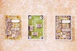
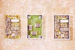
At the final assembly stage, the printed-wire board (PWB) is complete, with all surface-mount-technology (SMT) components reflow-soldered in place and only three power transistors missing (see Fig. 1). The PWB has nine empty through-hole connections ready to receive the leads from the three power transistors. The transistor packages are already bonded to the aluminum case, which acts as a heat sink. A pick-and-place machine just upstream of the soldering station drops the PWB into the case.
The tolerances are such that aligning the four mounting holes at the corners of the PWB on four mounting studs guarantees that the power-transistor leads will slip through the holes. Soldering the nine through-hole connections locks the PWB in place, ready for potting.
In the past, technicians made these final solder joints manually with a hand-held soldering pencil and wire solder while peering through a magnifier. "Six to seven technicians were required to keep up with the production line, which runs 24 hours a day," says ST controls engineering specialist Victor Trotter. "So, figure three shifts times six people, and they just couldn't keep up!"
In addition to issues of process variability—too much or too little solder, too much or too little heat—and quality issues such as missed-joints and solder bridges, there were the human issues of fatigue, training, and workforce turnover. Finally, hand soldering creates contamination problems that must be resolved before the assemblies are potted. Trotter's task, therefore, was to provide a system with equally adept vision guidance and solder-manipulating capabilities that was able to perform the job at production-line speeds.
SOLUTION ARCHITECTURE
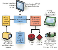
The vision-guided automated soldering system developed by ST incorporates three automated subsystems (vision guidance, motion control, and automated soldering) and a separate dumb video system (see Fig. 2). The centuries-old hot-soldering-iron technology was replaced by Softbeam technology from Panasonic that delivers energy to the solder joint in the form of an intense light beam.
The Softbeam system uses a 60-W high-pressure xenon arc lamp, which is focused onto a fiberoptic cable by a convergence mirror and delivered to the workpiece by a fiberoptic cable and convergence lens. The system controller allows automatic adjustment of the beam intensity by adjusting the lamp power and turning the beam on or off by opening or closing an electrically operated mechanical shutter.
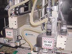
The vision system cannot reliably locate the solder pads on the module to be soldered until a heating block lifts it 0.020 in. (0.508 mm) off the pallet in the final soldering station. Earlier, there is too much opportunity for the PWB—which is loose in the module—to move around while being transported from station to station. At the soldering station, the heating block incorporates a vacuum chuck to ensure that the module does not move until the soldering operation is complete (see Fig. 3).
VISION GUIDANCE
The vision-guidance system incorporates CAD data to help navigate the soldering lens to the joint to be soldered. To make robotic assembly reliable, the placement tolerances were made relatively large—the module designers made the holes into which the locating pins fit large enough that the board would slip into place even if incorrectly located by as much as 0.020 in. (510 µm). As a result, the PWB can float around by that distance until soldered in place.
Conventional vision-guidance practice would have the vision system resolving each of the holes individually to guide the soldering head to it. Nine holes to find on each module means nine regions of interest, each of which had to be analyzed to extract coordinates. Trotter, however, saved processing time by taking advantage of the tight manufacturing tolerances of the PWB. As a fine-pitch SMT board, the manufacturing tolerances of the PWB are much tighter to make the component leads reach their solder pads. Many of the solder pads are smaller than 500 µm.
The vision-guidance system starts by imaging the PWB as it sits in the module case using a Panasonic GP-MF602 1/2-in. CCD color micro camera with NTSC head. The vision controller, an Adept-
Vision sAVI Inspection System, finds preselected fiducials whose positions and orientations provide a coordinate system fixed in the PWB. Using proprietary software, the machine calculates the transformation between PWB coordinates and its own coordinate system. In this case, the transformation involves only a single rotation and a displacement.
The fiducials can be any conveniently located features that are easy for the image-processing algorithm to find in the image. Essentially all that is needed are two high-contrast edges (which define two lines) oriented in different directions. Calculations are more accurate if the two edges are perpendicular to each other but that is not necessary.
COORDINATING DATA
From CAD data describing the PWB, the system can calculate displacements from the coordinate origin to the locations of the nine holes in PWB coordinate space. Actually, determining these vectors is part of the setup process for the particular PWB type to be assembled. Once they are known from the CAD data, they stay the same for all instances of the PWB. The system can then transform those joint locations from PWB coordinates to machine coordinates.
Finally, to drive the soldering head from one spot to the next, the machine forms the vector difference between the ending location and the starting location in machine coordinates. The automated x-y motion-control system moves the soldering head to the new location. Once there, however, the motion-control system must turn the head to an orientation that provides clear access to the joint for the solder wire, the heating beam, and a second camera that monitors the soldering process for each joint. It's important that the view of these components not be blocked by neighboring components.
features, advantanges, benefits
Hand soldering the final pieces of a printed-wire board in a switching-supply module can be error-prone and inefficient, which led an electronics-assembly plant to switch to a light-based soldering system teamed with machine vision. "These new machines have so far run 24/7 for probably a year and a half," says Spectra Technologies controls engineering specialist Victor Trotter. "Training has been almost a nonissue."
"We were able to train operators in four hours," says Trotter, "and we were able to train maintenance and setup people in a day. That performance was because of the operator interface. If you put something in front of people that's robust, well done, and tells them the information they need to know, they're usually going to do the right thing."
Company Info
Adept Technologies, San Jose, CA, USA www.adept.com
Dell Computer, Austin, TX, USA www.dell.com
Computar, Commack, NY, USA www.cbcamerica.com
Panasonic, Secaucus, NJ, USA www.panasonic.com
Sharp Electronics, Mahwah, NJ, USA www.sharpusa.com
Spectra Technologies, Euless, TX, USA www.spectratechnologies.com
Viewtronics, Bargteheide, Germany www.viewtronics.com


