Add-on peripherals augment Camera Link benefits
Camera and peripherals vendors are endorsing the Camera Link standard with a range of products that add to its usefulness.
By Andrew Wilson, Editor
In the past, RS-644 LVDS technology was the standard interface between high-performance cameras and frame grabbers. Designed to extend the performance of the RS-422 differential data bus, RS-644 LVDS provides clock rates of greater than 65 MHz and allows cable lengths of up to 100 ft to be accommodated. To transfer digital data using the standard, a pair of wires transmits each bit of data from the camera to the frame grabber. Because of this, vendors of high-speed, high-resolution, multiple-tap cameras required many cables that were often nonstandard, bulky, expensive, prone to breakage, and difficult to interface.
To overcome these limitations, OEMs have endorsed Camera Link, a standard based on the Channel Link LVDS chip set from National Semiconductor. Camera Link provides a standard connection between cameras and frame grabbers while at the same time reducing the cabling costs. Each Channel Link chip set consists of a transmitter and a receiver that allows 28 bits of data to be transferred over four pairs of wires at rates as high as 2.38 Gbits/s. By defining the connectors, cables, data format, and control signals in the standard, the task of the systems integrator is simplified.
After the development of the standard by a consortium headed by JAI Pulnix, the Automated Imaging Association (AIA) took over the administration and development of the Camera Link specifications. On the association's Web site, there is a current specification of the standard along with a Camera Link product-registration program that restricts the use of the Camera Link logo to registered products.
STANDARDS CONVERSION
Systems integrators who have already purchased cameras and frame grabbers that transmit and receive image data in either the RS-422 or RS-644 LVDS format can also take advantage of the benefits provided by the Camera Link standard. A number of vendors, including Basler, Image Teck, Imperx, and Vivid Engineering, offer interface devices that can convert data between different formats. This is especially useful for developers who wish to upgrade their systems without purchasing new cameras or frame grabbers.
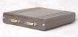
To interface RS-422 and LVDS digital cameras with Camera Link frame grabbers, the Vivid Engineering CLT-301 series of translators are available in a number of different versions (see Fig. 1). While the R and L versions support parallel RS-422 and LVDS digital-camera data, the M version supports the mixed RS-422/LVDS interface found in some Megaplus cameras from Redlake.
Image Teck also targets the Redlake Megaplus cameras with a converter kit that plugs into the 68-pin AIA digital cable connector on the rear of the cameras. The opposing Camera Link connector plugs into a Camera Link cable that, in turn, interfaces to a Camera Link frame-grabber board. The Imperx Adapt-a-Link series convert LVDS (RS-644) and RS-422 to and from the Camera Link-configuration interface.
Camera vendors also provide interface products that convert between older interfaces and Camera Link. Basler, for example, offers two types of interface converters for this purpose. The first, the b-BIC, converts the output from the company's Channel Link products, such as the A201b, a 1008 × 1018-pixel monochrome camera, to RS-644 LVDS. The second, the k-BIC, converts the output from its Camera Link cameras, such as the 2k L101k linescan device to RS-644 LVDS.
DIFFERENT CONFIGURATIONS
Using the Channel Link chip set, a 28-bit data path transfers data and control signals from the camera to the frame grabber. While 24 of these bits are used for data, four enable signals including Frame Valid (FVAL), Line Valid (LVAL), and Data Valid (DVAL), and a spare transmits signals from the camera to the frame grabber. For controlling the camera with signals such as external trigger and for serial communication with the camera, additional RS-644 drivers and receivers (CC1-CC4) are used. Camera manufacturers can define these four signals to meet their particular product designs.
The Camera Link Base configuration uses one Channel Link transmitter/receiver pair to transmit data over a 26-pin Micro Delta Ribbon (MDR) connector. These cables are currently available from vendors such as 3M Interconnect Solutions Division and Intercon 1.
For increased bandwidth, two Channel Link transmitter/receiver pairs are used in the Medium configuration, allowing 48 bits of data to be transmitted from the camera to the frame grabber. This requires two 26-pin MDR cables and connectors. In the Full configuration, three sets of transmitters and receivers transmit a theoretical 72 bits of video data also using two connectors.
Because Camera Link was never intended to be a plug-and-play specification, vendors still must write programs to support specific frame grabbers. Thus, when specifying a particular Camera Link camera, systems integrators should enquire which frame grabbers have been successfully interfaced with Base, Medium, and Full Camera Link-compatible cameras. Although some camera and frame-grabber vendors do list compatible cameras and frame grabbers on their Web sites, many do not, leaving this task to the systems integrator.
BASE, MEDIUM, AND FULL
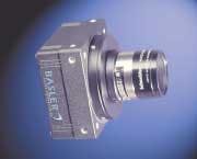
One of the most complete listings of cameras and compatible frame grabbers is available from Basler. Its A102k progressive-scan 1392 × 1040, 8- or 10-bit camera, for example, is a monochrome camera that is fully compatible with the Base Camera Link standard (see Fig. 2). Running at 14.2 frame/s, the area-scan camera also features area-of-interest scanning that allows the camera to capture images at higher frame rates. According to Basler, the more than 10 Camera Link-based frame grabbers supported by the camera include the DT 3145 from Data Translation, the GrabLink Value and Expert from Euresys, and the IMAQ-1428 from National Instruments.
To implement the Medium camera configuration, Camera Link camera vendors must employ two Camera Link connectors in their designs. Such a configuration is used by Dalsa in its latest HS-41, a Medium configuration Camera Link camera that provides a sensitivity of up to 1610DN/(nJ/cm2). According to Mark Butler, product manager, the camera has TDI and incorporates a 2048-pixel sensor with up to 64 stages of exposure. Line rates exceed 52 kHz. Dalsa claims that the HS-41 is compatible with "any" Medium Camera Link frame grabber and is provided with an F-mount adapter or M42 × 1 thread.
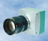
Having an imager featuring 1280 × 1024 pixels, the MC1310/11 from Mikrotron is an example of a CMOS camera with a Full 64-bit Camera Link interface (see Fig. 3). In operation, window size, position (ROI), and clock frequency are randomly programmable via the Camera Link interface, allowing eight sets of camera-configuration schemes to be stored in the camera's nonvolatile memory. To allow image preprocessing to be performed in the MC1310/11's FPGA hardware, FPGA configuration files also can be downloaded. With a pixel clock of 33 MHz on the Base Camera Link connector and a window size of 100 ( 100 pixels, a frame rate of more than 4.850 frames/s can be achieved. Maximum video data rate at the 64-bit Full Camera Link connector is 660 Mbytes/s.
To interface the camera to PC-based systems, developers can choose from a number of compatible frame grabbers. According to Karl Machunze, Mikrotron sales and marketing manager, these include the Mikrotron PCI-X based Inspecta-5, the Coreco X64, the Matrox Helios and Odyssey Xpro, the PLD Applications PCI-X XSYS, the Datacube MaxRevolution, and the I/O Industries DVR Express.
Vendors currently must write programs to support each specific frame grabber. However, according to Tony Iglesias, a software engineer with the machine-vision group of National Instruments, that's about to change. Two application programming interfaces (APIs) for asynchronous serial reading and writing were delivered to the AIA in January and, says Steve Kinney, JAI Pulnix product manager, will be available to AIA members before the next meeting at The Vision Show East (May 4–6; Boston, MA, USA). Provided there is consensus, the code should be implemented immediately following the show.
These APIs will allow frame-grabber-independent camera-configuration utilities to be created and provide manufacturer-specific information of serial communications functions. For more information, contact Jeff Fryman at [email protected].
DISTANCE LIMITATIONS
To span camera-to-frame grabber cable distances beyond the typical limit of 10 m, a number of companies have introduced Camera Link-to-fiberoptic extenders. These include modular products from Arvoo, 1st Vision, and Logical Solutions and add-in boards from Engineering Design Team and PLD Applications that can extend this distance to kilometers and beyond.
Systems developers should check each company's Web site to understand which cameras and frame grabbers have been successfully tested with each fiberoptic extender. The Logical Solutions site, for example, lists a number of cameras and frame grabbers that have been successfully integrated with its Camera Fiber-Link modules that permit the placement of a digital camera up to 500 m from the host computer.
Interestingly, in its first incarnation, the 1st Vision CLX10DER had fiber directly attached to the transceiver. But, according to the company, it became apparent that the fiber often needed to be routed through conduit, and pulling the 2-in.-wide transceiver through conduit was difficult. In addition, the original design used eight fibers for the control, serial communication, data, and clock signals, and excessive skew between the Camera Link data and clock signals caused faulty reception at the frame grabber. Therefore, the company redesigned the unit and introduced the CLX10DER-LC, which uses a detachable single duplex LC-style fiberoptic cable, allowing transmitter and receiver modules to be separated by hundreds of meters (see Fig. 4).
Using its second-generation fiberoptic interface, the EDT PCI-based add-in board, the DV-Fox, allows one to four cameras to be remotely located up to 300 m from the host PC and up to 10 km with an extended range option. To use the PCI-add-in board, an EDT RCX module first converts the camera's LVDS/RS-422 or Camera Link signals to a fiberoptic interface that then communicates with the add-in board. According to Arvoo, it is also possible to use two RCX modules as a fiberoptic "extension cord." In this configuration, digital camera data submitted to one RCX module are replicated at the output of a second RCX module. This feature will be implemented soon.
With several peripherals, cameras, and frame grabbers now supporting the Camera Link standard, many systems integrators are hoping that the standard is extended further to incorporate the features found in Dalsa's nearly four-year-old Camera Link Implementation Road Map. This includes a method for formatting output data in several ways to broaden the choice of frame grabbers that support specific cameras, in addition to proposals for an automatic camera/frame-grabber configuration capability.
Unfortunately, as one frame-grabber vendor points out, committees tend to move very slowly. And, for all its faults, the Camera Link standard does specify a standard camera-to-frame-grabber interface that eliminates the time-consuming task of developing specialized cables for each individual camera or frame grabber—a task that has already saved systems integrators and vendors thousands of hours of work.
Company Info
Due to space limitations, this Product Focus does not include all of the manufacturers of Camera Link cameras. For information on other suppliers, see the Worldwide Industrial Camera Directory (Sept. 2003) or theVision Systems DesignBuyers Guide (Feb. 2004), both available on the Web: www.vision-systems.com.
Arvoo, Woerden, The Netherlands www.arvoo.com
Automated Imaging Association, Ann Arbor, MI, USA www.machinevisiononline.org
Basler, Ahrensburg, Germany www.baslerweb.com
Coreco, St. Laurent, QC, Canada www.coreco.com
Dalsa, Waterloo, ON, Canada www.dalsa.com
Datacube, Danvers, MA, USA www.datacube.com
Data Translation, Marlboro, MA, USA www.datatranslation.com
Engineering Design Team, Beaverton, OR, USA www.edt.com
Euresys, Angleur, Belgium www.euresys.com
1st Vision, Andover, MA, USA www.1stvision.com
Image Teck, Encinitas, CA, USA www.imageteck.com
Imperx, Boca Raton, FL, USA www.imperx.com
Intercon 1, Baxter, MN, USA www.nortechsys.com/intercon
I/O Industries, London, ON, Canada www.ioindustries.com
JAI Pulnix, Sunnyvale, CA, USA www.pulnix.com
Logical Solutions, Milford, CT, USA www.thinklogical.com
Matrox, Dorval, QC, Canada www.matrox.com
Mikrotron, Eching, Germany www.mikrotron.de
National Instuments, Austin, TX, USA www.ni.com
National Semiconductor, Santa Clara, CA, USA www.national.com
PLD Applications, Aix-en-Provence, France www.plda.com
Redlake, San Diego, CA, USA www.redlake.com
3M Interconnect Solutions Division, Austin, TX, USA www.3m.com
Vivid Engineering, Shrewsbury, MA, USA www.vividengineering.com


