Choosing illumination for vision systems
Spectral content of source and lighting geometry are two key determinants of contrast and should be addressed early in the system-design process.
By John J. Merva
Lighting is traditionally the last component chosen when putting together a machine-vision system. After all, lighting is so simple, why worry about it while bigger problems such as hardware and software or optical components dominate the planning process?
Attitudes about lighting have been formed from years of experience with light in everyday life. The skills developed serve well for human vision but leave designers ill prepared to solve machine-vision illumination problems unless the physical phenomena that are occurring are understood. Recognizing the importance of illumination can lead to simpler, easier, and less costly solutions.
In every machine-vision application there are features of interest in the scene to identify, measure, or locate. As system designers and implementers, we must ensure that these features have sufficient contrast compared to other, unimportant features in the scene. When choosing lighting for the application we are making a decision that will affect image contrast as much as any other single component. Obtaining this contrast in the image should be the primary concern at the onset of the project.
Using this logic, we should choose the lighting at the beginning of the system-design process. First, the correct choice for hardware and software may not be possible until image contrast levels are known. Why pay for expensive, sophisticated processing if a high-contrast image doesn't require it? Conversely, even the most sophisticated and powerful vision system cannot reliably process an image with poor feature contrast. Second, lighting must be determined before the installation envelope is fixed. Proper illumination may not be possible if options for installing the correct light in the system have been eliminated by the location of other mechanical components.
Lighting source
How do we choose the light source? All machine-vision systems perform their analysis only after an electronic image is captured by the system. The image stored by the system represents how light reflected from the object is measured or recorded by the camera sensor. The image formed is a direct result of
Spectral content of the source: the color or spectral content of the light illuminating the object
Lighting geometry: location of the light source relative to the part and the entrance pupil of the optical system
Lens/optical system: optical system spectral characteristics such as distortions and modulation transfer function
Camera sensor: including the spectral sensitivity of the camera sensor and its resolution.
In this list only two items refer to the light source: the spectral content and geometry. So there are just two criteria to modify to create proper image contrast. Recognizing this fact, we can organize our approach to solving the problem.
Spectral content refers to which wavelengths of light exist in the light source. White lights contain wavelengths that include most or all the visible spectrum, which extends from around 400 to 700 nm. The Sun is the most perfect example of white light, as it has almost even amounts of energy for all of the visible wavelengths. Most machine-vision systems are black and white, or gray scale, and not color. If so, why does spectral content matter?
The answer to this question is that colors reflect wavelengths of light that are equivalent to that color. A red object in the sunlight is only reflecting red wavelengths (~660 nm). Because a gray-scale system shows us only intensity of light and not the color, illuminating a red object with any color but red will result in that object being darker in the image because there are no red wavelengths for the object to reflect.
This phenomenon allows us to make use of the color wheel to determine what color to use in illuminating objects (see Fig. 1). Utilizing light that is the same color as an object makes it brighter in the scene. Light that is an opposite color makes that color appear darker. For example, red light makes green objects appear dark. Green light makes green objects appear bright.
Geometry
Geometry refers to the source of the light relative to the part and the entrance to the optical system. Lighting geometry is used to complement human sight in everyday life. When you move an object around in your hands to observe different features, you are changing lighting geometry. Likewise, when adjusting the surface of a glossy magazine so that the glare disappears, you are adjusting lighting geometry, moving from bright field to dark field.
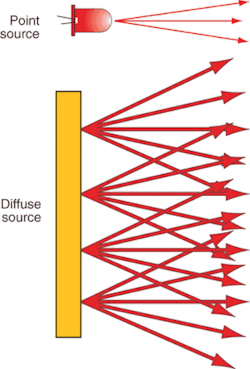
Light can come from point sources or diffuse sources (see Fig 2). The Sun is an excellent example of a point source while the sky on a cloudy day is an example of a diffuse source. Point sources often create glare and strong shadows, while diffuse sources tend to eliminate shadows and reduce glare. Think of the experiences outside while driving or looking across bodies of water. The same results occur in a vision system.
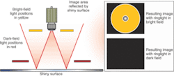
Bright field and dark field are two other important geometric lighting concepts. For practical purposes these concepts only matter when dealing with shiny (specular) surfaces. The rule is straightforward: when imaging a shiny surface, if you can see the light reflected in the image (glare), the setup is in bright field. If not, then the setup is in dark field (see Fig. 3).
When imaging shiny, or specular, surfaces, the single biggest problem is creating an image that is partially in bright field and partially in dark field. The bright-field areas will exhibit glare or saturation. The dark-field areas will be very low in intensity. The result is that the image created has large variations in intensity creating unwanted contrast or visual noise. An image with this problem will almost always be unacceptable for processing, even with the most powerful system.
JOHN J. MERVA was with Advanced Illumination, Rochester, VT, USA, at the time this article was written; www.advancedillumination.com.


