Vision-guided robot dispenses liquid gasket
By calculating 3-D location and orientation of parts, software guides the dispensing of sealant along auto-part flanges.
By Colin Scott
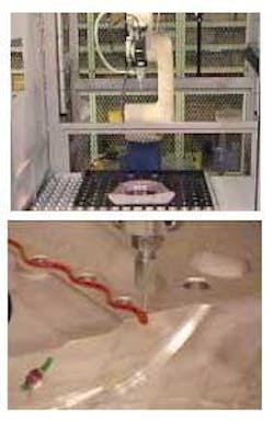
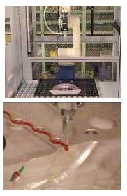
Hino Motors, an affiliate of Toyota, asked Marubeni to develop a liquid-sealant-dispensing application for a manufacturing line in one of its Tokyo manufacturing plants. In the application, a robot applies a liquid gasket onto mating flanges of up to 10 different types of parts, ranging from engine blocks to transmission parts including flywheel housings, retainers, breather pipes, and cooling water manifolds. The application requires dispensing a finely metered bead of sealant along a precise path on the part flange. This is a highly critical operation since an improperly positioned bead or variations in the bead size can lead to oil or water leakage in the engine.
To make sure the bead is both properly positioned and proportioned, the precise 3-D location and orientation (3-D pose) of each part must be known to the dispensing robot. This pose information ensures that the bead is dispensed correctly relative to the features on the flange (for example, holes and edges). Also, knowing the 3-D pose of the part means that the intended height between the dispensing gun and the surface can be maintained, thus allowing fine control and consistency of the bead size (see Fig. 1).
Marubeni developed a robot-guidance system that consists of a Denso Robot VS-6577E; a Sony XC-E150 CCD camera; infrared lighting; a PC-host Pentium IV, 2.4-GHz, 256-Mbyte PC; Windows 2000 OS; Matrox Meteor-II frame grabber; and Braintech eVisionFactory (eVF) development and runtime vision-guided robotic (VGR) software platform.
A conventional robotic dispensing system would have required unique fixturing devices for each part to ensure it was in the same position and orientation each time the robot began its cycle of dispensing the liquid gasket. These fixtures would have to be custom designed and manufactured for each part and maintained over time, resulting in high capital and maintenance costs. Hard-tool fixtures are also inflexible and cannot be reprogrammed to process new parts, adding to changeover times. Marubeni determined that hard-tooled fixtures could be eliminated by installing the Braintech VGR platform.
Automating the process
Calibration between the vision system and the robot is performed when the vision system is initially set up using the eVF automated calibration technology—AutoCal-3-D. Typically, manual calibration of 3-D VGR systems is a multistep process requiring training and knowledge of both the robot and the vision system. The process is time-consuming because of safety precautions and error prone because of its manual and subjective nature. Depending on the level of operator training, the entire calibration process can take between 20 and 40 minutes. Calibration must be repeated if the robot end effector has a collision and when changes are made to the camera or lens.
In contrast to manual calibration, AutoCal-3-D places the calibration pattern at any point within view of the robot-mounted camera; then the robot is placed in automatic mode and the program moves the robot to successive viewpoints, taking an image at each point. In fewer than 10 s, the vision and robot coordinate frames are calibrated.
Single-camera 3-D
To begin, an operator manually positions a part in front of the robot and then hits a start switch on the robot controller. Communication between the robot controller and the vision PC is transmitted over an RS232C serial communication line. The eVF software, resident on the PC RAM, detects the robot's request for guidance information and executes a specific eVF job for each type of part. The job enables the robot to visually identify the part and determine the exact 3-D pose of the part so the path of the robot can be adjusted to dispense the sealant (see Fig. 2).
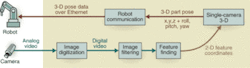
In each job, the robot-mounted CCD camera takes a single still image and transmits the information to eVF. The single-camera 3-D (SC3-D) algorithms then calculate the full 3-D location of the part—including all six degrees of freedom (x, y, z, and roll, pitch, and yaw angles). Pattern-matching algorithms are used to search the processed image for key part features.
The Sony XC-EI50 CCD near-IR camera was chosen because of its compact size and resistance to shock. The camera uses standard VGA resolution (640 × 480 pixels) and a bit depth of 8 bits/pixel. The combination of IR lighting and a bandpass optical filter significantly reduces the effect of ambient light.
Features are identified in the image with various degrees of confidence or probability of match using edge-detection and other algorithms. Features that are found with a confidence level below a preset threshold are deemed suspect and discarded, while the remaining features are labeled as qualified. In the Hino applications, eVF must find a minimum of five qualified features to determine a 3-D pose (see Fig. 3).
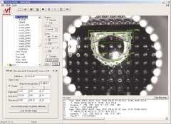
The image coordinates (cartesian space) of the qualified features are input into the SC3-D algorithms, which analyze them and use apparent variations in the geometric relationships between the positions of features to calculate the three-dimensional pose of the part in a virtual 3-D coordinate frame. The translated 3-D pose of the part is sent to the robot controller over RS232C serial communication line along with a job-complete signal. The robot controller then uses the new coordinates of the part to adjust the points constituting the path to approach and engage the part. From this point, the Denso robot program takes over, lays the sealant bead, and completes the task.
COLIN SCOTT is a technical writer at Braintech, North Vancouver, BC, Canada; www.braintech.com.
Company Info
Braintech, North Vancouver, BC, Canada, www.braintech.com
Denso, Aichi, Japan, www.denso.co.jp
Hino Motors, Tokyo, Japan, www.hino.co.jp
Marubeni, Tokyo, Japan, www.marubeni.co.jp
Matrox, Dorval, QC, Canada, www.matrox.com
Sony, Tokyo, Japan, www.sony.net