Cameras inspect piston rings
By Andrew Wilson, Editor
A Michigan-based, tier-one, global supplier of automotive components and subsystems for OEMs and the after-market offers hundreds of automotive components including cast-aluminum, cast-iron, and steel piston rings and pins. Before each piston is packaged and shipped, several key features of the piston must be thoroughly inspected. These inspections check the proper insertion of the piston's circlip or snap ring, oil-ring, orientation of the piston rod, and presence of a witness mark that verifies the piston has been correctly inspected.
For help in accomplishing these tasks automatically, the supplier turned to Advanced Control Solutions (ACS; Marietta, GA), a distributor of automation products such as PC-based controls, intelligent sensors, and machine-vision, motion-control, networking, and motor-control devices. Founded in 1996 as a distributor for DVT Corp. (Norcross, GA), ACS soon realized that its customers required more than the delivery of vision parts and that it would have to take on more responsibility for the success of its vision and automation systems. "ACS's use of the DVT customer model to train and support users is important to the success of vision projects," says David Hicks, DVT business-development manager.
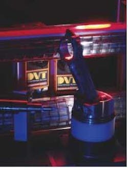
"The ACS piston-inspection system started as a simple circlip-inspection system," says president Dave Pilliod, "and it evolved into a system that can perform other functions such as oil-ring inspection, orientation of the piston rod, and checking for the presence of a witness mark" (see Fig. 1 and front cover). ACS supplies pistons to the three largest automotive makers, as well as to engine manufacturers of lawnmowers, generators, and pressure washers.
null
In the past, the pistons were manually inspected and placed on palettes for shipment to engine builders. If a single piston was judged suspect by the engine builder, it would return the complete palette to the piston manufacturer for re-inspection. "This manual inspection process was so prone to errors," says Pilliod, "that hundreds of parts were returned each month." Rejected parts were so pervasive, in fact, that supply contracts were in danger of being canceled, according to Pilliod.
A major reason for the replacement of manual inspection was that subtle differences in piston types cannot be easily discerned by human eyes. And, because pistons are produced at the rate of one every ten seconds, their inspection by human operators is neither fast nor accurate enough. To solve these problems, ACS was charged with automating the procedure with a vision system that performs numerous inspection functions with high accuracy and repeatability.
Piston inspection
To perform an inspection, an operator unloads a piston from the manufacturing line and loads it into a fixture in the ACS piston-inspection system. A Safe4 safety light curtain from Cedes (Landquart, Switzerland) starts the inspection process as the operator's hand passes through the light. The Safe4 curtain exceeds all safety standards according to machinery directive EC/98/37 and respective IEC standards. The light-curtain's microcontroller sends a signal to an Ultimate I/O controller from Opto 22 (Temecula, CA).
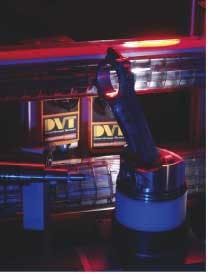
In turn, the I/O controller transmits a signal to an FM-4 control module from Emerson Control Techniques (Eden Prairie, MN). The control module governs the motion profile to an EN-Servo drive, also from Emerson, where the piston is placed in a rotary-actuated turntable with a vacuum chuck to secure the piston (see Fig. 2). The module initiates programs to sequence motion and I/O control and features removable terminal block connectors for I/O signals and a sync cable for master encoder connections. It targets applications that deal with complex motion profiles and is programmed in the company's Powertools Pro language. "Because the FM-4 features encoder capture," says Harris Jones, ACS project engineer, "the piston's positional information is captured and repeatable to within 0.2°."
null
Before a visual inspection can take place, the exact position of the piston must be known. To properly locate the piston, a through-beam laser sensor from Balluff (Florence, KY) projects a laser light through a hole in the shaft of the piston. A microreceptor (also from Balluff) on the opposite side of the fixture then detects the exact angle of the piston's placement in the housing. "Once this angular information is known," says Jones, "the FM-4 can be programmed to properly position the rotary stage and trigger four inspection cameras at the correct rotational orientation."
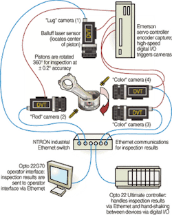
The images captured by these four cameras determine whether the piston has passed or failed inspection. A camera located above the fixture looks down on the housing for the location of a lug on the piston. This "lug" camera, a DVT 540, features built-in Ethernet connectivity and an SH4 processor from Hitachi Semiconductor (San Jose, CA) that boosts the image digitizing time to 13 ms. Ethernet connectivity passes data-acquisition, imaging data transmission, and image-processing results through an 900B Modular Industrial Ethernet Switch from N-TRON (Mobile, AL) to the Opto 22 Ultimate controller.
By measuring the position of the lug on the piston, the camera's smart sensor determines the orientation of the piston in the fixture. "If, for example, the piston is loaded with a piston rod aligned to the left," explains Jones, "a similar image would be obtained by rotating the image by 180° and moving the rod from right to left (see Fig. 2). However, the position of the lug would then be different. This is what determines the orientation of the piston in the fixture."
After the piston orientation has been determined, the data are transmitted over the camera's Ethernet link through the N-TRON Ethernet switch to the Opto 22 controller and ultimately to a second DVT 540 camera. This "rod" inspection camera determines whether the proper face of the piston rod is presented to the camera. Says Jones, "There could possibly be two piston-rod faces presented to the second camera—the proper orientation and the incorrect one. But because the system has already computed the piston's lug position, the second "rod" camera can easily check which rod face is presented to the camera; this verifies whether the piston has been correctly assembled," he adds.
Rings and circlips
As the piston is rotated by the EN-Servo drive, the piston rings and circlip are inspected for proper insertion and correct placement. To do this, the system uses a third smart sensor, a DVT 542C color camera that offers a 1/4-in. format CCD, 640 × 480-pixel resolution, and electronic shuttering from 10 µs to 1 s. As the piston rotates, an image of three piston rings is captured every 10°, resulting in approximately 38 inspections. These results are transmitted via Ethernet to the Opto 22 Ultimate controller (see Fig. 3).
null
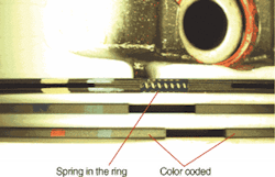
"On every piston, three rings are checked for correct placement. A spring is placed in the top ring to keep pressure on the cylinder after placement in the engine block. In the process of examining ring placement, the presence of this ring must also be determined," says Jones. To perform this task, the color camera analyzes the sequence of color bands in the piston rings by a series of captured images. "As each color sequence is different for each piston ring, an analysis of the color sequence provides a means to determine whether the correct ring has been emplaced," says Jones. By comparison, the presence of the piston spring in the topmost ring also provides its own image signature, which is used in a similar manner to determine the presence or absence of the spring.
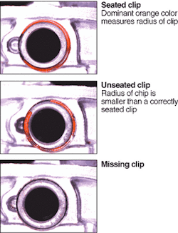
While this inspection is taking place, a fourth DVT 542C color smart sensor determines the presence or absence of the piston's circlip and whether it is properly seated in the piston ring. "Previously, a gray-scale camera from another maker was used to perform this function," says Pilliod. "Unfortunately, in using and analyzing the gray-scale images captured with this camera, the inspection system failed consistently to determine the presence/absence or seating of the circlip. In the ACS system, the DVT 542C camera successfully analyzes the dominant orange color of the circlip and measures the radius of the clip. If the radius of the clip is smaller than a clip that is properly seated, then the system detects the presence of an unseated clip. If the system does not detect the presence of the dominant orange color, then the likelihood of a missing clip is high (see Fig. 4).
null
Piston analysis
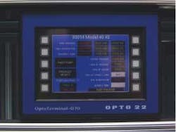
All the vision-inspection functions are performed and the results are transmitted via Ethernet over the N-TRON Industrial Ethernet switch to the Opto 22 Ultimate controller. Here, all the individual tests are correlated and analyzed, and a pass/fail decision is made. If a part is graded as a failure, the inspection system stores a complete description of which test failed. These data are then transmitted again over the Ethernet to an OptoTerminal-G70 operator display from Opto 22 (see Fig. 5). This 21 × 16-cm mountable display terminal features a standard Ethernet port, a 14-cm-diagonal screen, 320 × 240-pixel resolution, and a color touchscreen display that sends commands and receives data from connected Ethernet devices.
null
The OptoTerminal-G70 is programmed with custom Opto 22 software that provides an object-oriented programming environment for application design and integration. The software comes with a custom object library that includes text, geometric shapes, buttons, gauges, grids, meters, and graphics that can be sized, scaled, and placed to the user's specifications. "By assigning attributes to each object and defining their functionality, intelligent applications with event-alarming features can be created without having to write complex code," says Jones. "This simplifies operator interface development."
When a part passes every inspection, an inkjet marker, fired by the controller, places a green witness mark on the side of the piston head. The inspection system is then restarted, and the color circlip camera determines whether the mark has been placed on the piston. If the witness mark is properly identified, the system operator is instructed to remove the inspected piston and place it on a palette for shipping. "All the part inspections, marking, and re-inspection happen in eight seconds," says Jones. "The system performs these functions as the pistons emerge from the manufacturing line at the rate of one every ten seconds," he says.
Costing less than $150,000, the first system has been operational for six months. "Since the system has been installed," says ACS's Pilliod, "there have been no shipments from the manufacturer that have been returned from a customer," he says. "And, because of the success of the first system, the manufacturer has ordered a similar system," he adds.
The implementation of the manufacturing-automation system will ultimately involve more than just piston inspection. "The final goal for the plant engineer," says Pilliod, "is to install four such machines and replace the operator with a robot that will load parts onto the test fixtures directly from the production line, 24 hours a day, seven days a week."
Company Information
Advanced Control Solutions
Marietta, GA, USA
www.acs-ga.com
Balluff
Florence, KY, USA
www.balluff.com
Cedes AG
Landquart, Switzerland
www.cedes.com
DVT Corp.
Norcross, GA, USA
www.dvtsensors.com
Emerson Control Techniques
Eden Prairie, MN, USA
www.gotoemerson.com
Hitachi Semiconductor (America)
San Jose, CA, USA
semiconductor.hitachi.com
N-TRON
Mobile, AL, USA
www.n-tron.com
Opto 22
Temecula, CA, USA
www.opto22.com
