Imaging systems confirm switch integrity

A vision inspection system integrates off-the-shelf components to check assembly of automotive switches.
By Andrew Wilson,Editor
Today's automotive industry is mandating a number of highly automated assembly processes to save labor, time, and cost. For many consumer vehicles, automotive plants are already using vision systems to inspect engine components, body parts, and automotive parts. Specialized vehicles, such as delivery vans and snowplows, however, need more-demanding electronic control systems to direct special operations such as salt and sand dispensers. Accordingly, custom switches, pushbuttons, and controls must be designed, tested, and implemented inside these vehicles.
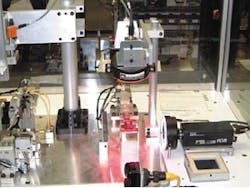
FIGURE 1. After the pneumatically controlled machine seals the components into a finished assembly (left), the surfaces of the switches are inspected for correct visual characteristics. Simultaneously, the position and color of the switch actuator are digitized and computed (right). (Photo couresy of Automated Technologies Corp.)
For example, Pollak (Canton, MA) makes special switches for the custom automotive industry. These switches are unlike those found in consumer automotive vehicles. Rocker-based, these switches are used in industrial vehicles.
For these vehicles, the customer specifies how these controls (often switches) are to be constructed, used, and located. Because operator control panels in these vehicles are often complicated, switch arrangements must be user-friendly to the operator. Moreover, during the assembly process, each switch in its housing must be correctly labeled and located in the proper switch box.
Automation technologyTo meet these stringent demands, Pollak contracted Automation Technologies Corp. (ATC; Cranston, RI) to develop a semi-automated system to both assemble and check the positions of these switches. ATC was tasked to build a semi-automatic system to assemble a switch from such components as an actuator, spring plunger, button, and housing. During assembly, these components are placed manually within a test fixture. Then, a pneumatically controlled machine automatically seals the components into a finished assembly (see Fig. 1).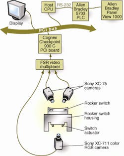
FIGURE 2. Images of the top of the switch assemblies are digitized by two monochrome cameras while color images of the switch actuator are captured by an RGB camera. Outputs from these three cameras are fed into a video multiplexer and then digitized by an image-processing board for further image analysis.
Finished switches are manually taken from the automated assembly system and placed in another test fixture. Here, the switches are automatically inspected by a PC-based vision inspection system. This system inspects both the visual characteristics of the information on the front of the switch and the actuator component using off-the-shelf imaging components from several different vendors.
"In the design of this system," says John Healey, ATC senior project manager, "we analyzed a number of different off-the-shelf imaging systems, including those from RVSI Acuity (Canton, MA) and Cognex (Natick, MA)." The most important goals were to determine whether the visual characteristics on the face of the switch were correct and whether the correct actuator had been installed. To meet these goals, pattern-matching software played a key role. "Because of these factors," says Healey, "we chose to implement the Checkpoint system from Cognex as the tool to perform the visual inspection."
Lights, camera, visionDuring switch inspection, positioning of the system cameras and lighting is extremely critical. The switch under inspection is initially placed in a test fixture where it is illuminated and imaged by three lighting and camera systems. To image the surface of the switch, two red-light-emitting-diode (LED) ringlights from Advanced Illumination (Rochester, VT) are placed at a 15° angle to the horizontal. This positioning allows the camera system to image the entire surface of the rocker switch.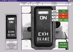
FIGURE 3. Each switch assembly under inspection is manually placed into a test rig. An intensity profile of the switch assembly is then generated and compared with the correct image stored in the database. If this intensity difference is completely black, then there will be a 100% correlation between the part under test and the part in the database and the part will pass (right). If the inspection system discovers differences, the part will be highlighted as failed (below).
"By using a two-camera setup," explains Healey, "paddle switches that could block one side of the switch's view to one camera can be easily imaged by the other camera." To illuminate the color of the switch actuator, a white LED ringlight, also from Advanced Illumination, illuminates the underside of the switch assembly.
Monochrome images of the top of the switch are acquired and digitized by two XC-75 CCD RS-170 cameras from Sony Electronics (Park Ridge, NJ). Similarly, red-green-blue (RGB) images of the switch actuator are captured by a Sony XC-7111 RGB camera. Before digitization and image processing can be performed, the outputs from the three cameras are fed into a video multiplexer from FSR (West Patterson, NJ). The output of the multiplexer is then passed on to the PCI-based Checkpoint 900C board from Cognex (see Fig. 2). Here, individual images can be selectively digitized under computer control for image analysis.
On the topCognex PatMax software is used to confirm that information is placed on top of the switch and the color actuator is present. Before any visual inspection of the surface of each switch can take place, a database of more than 50 switch images was developed in Microsoft Data Base format, an access format used by database programs such as Dbase and FoxPro software."After images are stored in this format," says Healey, "they can be accessed using Microsoft's Visual Basic software. The technician performs such functions as database editing, changing part numbers, teaching the system to recognize parts (using PatMax), and performing off-line test runs of each image."
To generate a pattern for comparison with each test part, an image intensity profile is performed on every switch pattern in the database. This information is then stored in Cognex image database format by the system.
Next, each switch to be inspected is placed manually in the test rig, and the system is initialized. An intensity profile of the switch under test is generated and compared with the correct image stored in the database. "If this intensity difference is completely black," explains Healey, "then there will be 100% correlation between the part under test and the part in the database.
In practice, however, a 100% correlation is rarely the case. Factors such as image noise and dust particles result in clutter noise appearing in the difference image. "Because of this," says Healey, "the Cognex blob-analysis tool determines the size of small areas or blobs that may appear. In ATC's system, any blob greater than five contiguous pixels is registered, and the technician operator is provided with a visual indication of the area of the switch under test where this defect occurs (see Fig. 3).
Actuator imagingTo determine whether the correct color actuator has been installed in the switch housing, each actuator is compared with the correct color stored in the database. Four possible actuator colors can be installed into each switch—red, black, white, and blue. Each color and actuator position is checked before the switch passes this inspection. Once again, Healey chose Cognex's PatMax tool to locate the actuator in a bounding box (see Fig. 4).Once the actuator is located, Cognex's Lightmeter tool determines the color of the actuator in hue, intensity, and saturation color space. Results are passed to a classifier tool that contains the definitions of all four colors. "Here," says Healey, "five results can occur—either the system will match one of the four colors or there will be no result at all." Results of each individual inspection are then compared with the expected results, and a pass/fail condition is reported.
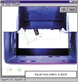
FIGURE 4. To determine whether the correct color actuator has been installed in the switch housing, the color of each actuator is compared with the color stored in the database. To do so, Cognex's PatMax tool locates the actuator in a bounding box and a Lightmeter tool determines the color of the actuator. Results are then passed to a classifier tool that compares the result of each individual inspection with the expected result.
In developing the actuator-inspection system, ATC also wanted to check whether the leg of each switch was present. "This was a trivial operation," says Healey. "By checking the intensity of the image at two points in the image [shown as two green boxes at the bottom right and left of Fig. 4], the system can rapidly determine whether a switch leg is present."
After the color of the actuator and the correct visual characteristics of the switch are checked, the switches are manually mounted into different bezel mounts. "In the specification of an industrial vehicle," says Mike English, ATC sales and marketing manager, "these bezel mounts are chosen by the customer." After such bezels have been fully populated, they are again subjected to visual inspection by ATC's e-bench final test system.
"After the switches are mounted in each bezel," explains Healey, "the final test system again uses PatMax to check whether the position of each switch in the housing is correct." Here, only the PatMax pattern-matching function is used because there is no need to retest the switch's visual characteristics.
In the final bezel mounting, the switches are also backlit by both green and LED lights. Therefore, when a technician sets a switch to either OFF or ON, light from the LEDs is illuminated through the switch housing to indicate the status of the system being controlled. Under control of LabVIEW software from National Instruments (Austin, TX), switches mounted in bezels are illuminated and verified using the Cognex Color Blob tool running on the e-bench system's Checkpoint board.
Pollak will use both inspection systems in conjunction with manual switch-assembly methods. According to the company, ATC's automated inspection systems will improve the efficiency and reliability of switch bezel mounts the company ships to auto manufacturers.
Company InformationAdvanced IlluminationRochester, VT 05767Web: www.advill.comAutomation Technologies Corp.
Cranston, RI 02920
(401) 736-3400
Cognex
Natick, MA 01760
Web: www.cognex.com
DVT
Norcross, GA 30093
Web: www.dvtsensors.com
FSR
West Patterson, NJ 07424
Web: www.fsrinc.com
National Instruments
Austin, TX 78759
Web: www.ni.com
Pollak
St. Paul, MN 55126
Web: www.stoneridge.com
RVSI Acuity
Canton, MA 02021
Web: www.rvsi.com
Sony
Park Ridge, NJ 07656
Web: www.sony.com