Researchers use computed tomography for auto-parts inspection
Computed tomography is making inroads into industrial inspection, such as in 3-D checking of large automobile engines.
By R. Winn Hardin,Contributing Editor
Introduced in the early 1970s as a new neurological-examination technique, the impact of computed tomography (CT) was so extensive that in 1979 Sir Godfrey Hounsfield and the late Allan Cormack, the inventors, were awarded the Nobel Prize in diagnostic medicine.
Since then, CT technology has been extended for implementation in many industrial applications. For example, medical systems use relatively low-energy x-ray tubes, generally at 140 keV (thousand electronvolts); however, such low-energy x-rays do not penetrate most mechanical objects. To overcome this constraint, industrial systems use x-ray sources up to 15 MeV (million electronvolts).
Industrial and medical CT systems do share some characteristics, however. Both create two-dimensional (2-D) transverse images (cross sections) of objects. These 2-D slices can then be stacked into a three-dimensional (3-D) model of the object. During a medical-scanning procedure, the patient lies flat on a gantry, and the gantry is slowly moved along the horizontal axis between the imaging source and the detector array.
Because of their large size, parts such as automobile transmissions and motors must be positioned on a stage that can be both translated and rotated to make x-ray transmission measurements at multiple angles and different positions. The detector array and the x-ray source head are elevated to collect individual computed-tomography images or slices in the vertical direction.
Industrial CT systems are mostly used to image large parts—that is, parts larger than the fan-shaped x-ray beam itself. Therefore, the "translate-rotate" method of data collection is typically used in such systems. In this method, the object is translated, or moved through, the x-ray beam. Full data sets are obtained by rotating the object between translations and again translating the information until a minimum of 180° of data has been acquired.
Industrial imaging
At its Powertrain Division (Livonia, MI), the Ford Motor Co. has installed an ICT-1500 industrial CT system from Aracor (Sunnyvale, CA). Slated for use in Ford's Nondestructive Evaluation Center, the CT system is expected to help optimize manufacturing processes and provide reverse engineering capability.
Aracor's ICT system resembles a medical scanner set placed on end. In this approach, the x-ray head and detectors are moved up and down to change the location of the inspection process. The mechanical system, which moves the detectors, x-ray head, and object, can move large and heavy objects at micron accuracy.
Consisting of an x-ray source, detector, and mechanical system under computer control, the CT system uses a 9-MeV x-ray source from Varian Medical Systems (Palo Alto, CA) that consists of an x-ray head, modulator, chiller, and control console. The pulsed stream of x-rays passes through the object and is captured by an array of cadmium tungstate (CdWO4) based scintillation detectors bonded to silicon photodiodes from UDT Sensors (Hawthorne, CA).
FIGURE 1. Typical Aracor industrial CT system uses two alpha workstations: one master computer and three monitors for scan setup, image display, and gantry monitoring, respectively, and a second alpha workstation with two monitors for display and analysis of CT images.
Arranged in an arc opposite the source head, the detectors convert the x-ray inputs into electrical signals that are amplified, conditioned, compensated, and integrated by a set of proprietary analog processor (AP) boards. Each board, located near the detectors, accepts two detector channels that are then multiplexed and connected to a set of proprietary analog-to-digital converter (ADC) boards via ribbon cables. The ADC boards are also located in the immediate vicinity of the detectors and AP boards. "Although these boards use a 16-bit ADC, the processor boards provide an automatic ranging capability that allows the CT system to produce digitized data over a 20-bit range," says Jim LePage, Aracor's chief scientist.
The signals from the ADC boards are sequentially sent to a Compaq/ DEC Personal Workstation 500 AU parallel port using a detector-array input/output board, which is connected to the ADC boards by ribbon cables and a proprietary scan-control interface that resides within a few feet of the master control computer (MCC). With a 500-MHz CPU, a 4-Gbyte internal hard drive, and 512-Mbytes of RAM, the MCC provides the operator interface, controls the scanning procedure, and reconstructs and displays images (see Fig. 1). Using two 21-in.-diagonal monitors for displaying the operator's graphical user interface (GUI), the system also supports a 17-in. monitor for displaying system status.
FIGURE 2. An industrial CT scan session typically starts with a radiograph that shows all the 3-D structures, both internal and external, in 2-D space. Through the use of computer-aided-tomography software and image-processing software, the Aracor ICT system can use that radiograph to help set up the actual CT scan, including regions of interest, resolution, and speed.
While the main workstation acquires data, another dual-screen 500 AU workstation, which is connected to the Ethernet, acts as an analysis computer. It performs image reconstruction, display, analysis, and archiving.
When acquiring data, the CT system makes between 368,000 and 15 million x-ray transmission measurements of the object at different locations and orientations. A mechanical gantry from Eimeldingen (Indianapolis, IN) helps to position the object for these measurements. It consists of a 1-m-diameter rotary table connected to a horizontal translation axis. This gantry is controlled by a programmable multiaxis controller from Delta Tau (Chatsworth, CA) and is interfaced to the Compaq/DEC Personal Workstation via an RS-232 interface. During the scanning process, the object is rotated, and data are translated through the x-ray beam as transmission measurements are acquired. Even though a large number of measurements are required, data to reconstruct a complete CT image can be acquired in less than two minutes.
System operation
Aracor's computed-aided-tomography software (CATS) controls the system and provides the system's GUI. Operating under the Digital/Compaq VMS operating system, the CATS is written in both C and FORTRAN and consists of four modules that acquire data, reconstruct CT images, and display, analyze, and archive images.
Before scanning, the parameters that govern the data-acquisition process, which include the field of view, elevation at which images are to be obtained, detector signal integration time, and detector collimator slice thickness and resolution aperture settings, are initially specified.
FIGURE 3. Although it does not reveal usable visible clues for determining internal structures, the first visual image from a CT scan—the sinogram—informs the technician if the x-ray source and detectors are working properly and if the part is positioned correctly. Black patches, representing missing data, indicate that the x-ray source or detectors are not working properly, while data near the edge of the sinogram disclose whether the part extends beyond the system's field of view.
Often, a digital radiograph is taken prior to acquiring CT data to locate regions of interest that require study (see Fig. 2). These 2-D images show all the internal 3-D structures of an object superimposed in 2-D space. Although such radiographs can be made faster than CT images, they are more difficult to interpret and contain less information than their CT counterparts. Once a feature of interest is identified in the radiograph, however, a CT slice can be made at that location.
During the CT data-acquisition period, the processed detector data are displayed in the form of a parallel beam sinogram (see Fig. 3). This 2-D image of the object's attenuation is displayed in the CT system's radial coordinate system. "Sinograms allow operators to determine if the x-ray source or detectors are working properly and if the part is positioned correctly in the CT system's field of view. While black patches indicate a faulty detector or missing pulses from the source, visual data at the edge of the sinogram indicate if the part extends beyond the system's field of view," says Harvey Peck, Aracor's vice president of imaging systems.
After data are acquired, 16-bit-deep CT images as large as 4k x 4k pixels can be reconstructed. On the Personal Workstation 500 AU, a 4k x 4k-pixel image takes 38 s for reconstruction; a 512 x 512-pixel image takes about 0.61 s.
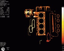
FIGURE 4. CT image comprises thousands of x-ray intensity measurements that are used to reconstruct a full 2-D cross section of a large part (in this case an automobile engine) under scan (top). CT data can be converted to several useful data sets, including STL files for rapid stereolithography prototyping across the Internet or CAD files through the use of programs external to Aracor's ICT system (left).
Image pixel intensities are displayed in units of grams per cubic centimeter. These values are approximately equal to the object's bulk density at that pixel location. By using calibration standards, density measurements can be made that are accurate to within a few percent. Because a CT image is a plot of the object's density, defects can be located and quantified. Boundaries between dissimilar materials within the object can also be established.
Because these boundaries can be located to within a few mils, CT image data can be used to measure object features such as hole diameter, location, and wall thickness. Image-processing functions include filters for edge sharpening and image smoothing, statistical measurements, dimensional measurements, graphing image data, and changing image-display contrast and range.
Images and data are stored in a binary format on the analysis computer's 18-Gbyte data disk. A 4.6-Gbyte magneto-optic disk drive and a 12-Gbyte digital audio-tape drive are provided for data storage in binary and TIFF formats. The system software maintains a database to retrieve archived information. Using the database, technicians can perform searches on key parameters such as part scan date, name, description, and serial number, as well as various image parameters such as aperture settings and image size.
Reverse engineering
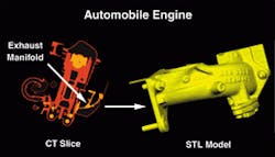
By using the CATS command language, inspection sequences can be created for automatic operation of the CT system. The 2-D CT images also can be automatically reconstructed and analyzed. A typical automatic scan sequence consists of performing a series of contiguous CT scans at slightly different elevations. By integrating these slices, a digital 3-D-density model of the part can be obtained. Using density data, a surface model of the part is then generated and saved in a stereolithography format used by rapid prototyping machines (see Fig. 4).
Unlike the 3-D models created with coordinate measuring machines, laser scanners, or CAD systems, models created from CT data can accurately model the internal flaws, defects, and dimensional irregularities of parts. These models can be used with finite-element software to determine how a structural defect might result in failure, how long it might take to fail, and with what effects.
"Up to now, the US Department of Defense and industry have used CT technology primarily for nondestructive inspection. The recent introduction of reverse engineering, metrology, and part-production software allows CAD designs to be produced by scanning a part. The 3-D metrology can be performed on a first-article part and compared to its CAD master. We can also convert CT data to standard-template-library files and use rapid prototyping techniques to produce tooling," says Aracor's president Bob Armistead.
Company Information
Aracor
Sunnyvale, CA 94086
(408) 733-7780
Fax: (408) 732-1996
Web: www.aracor.com
Compaq/DEC
Phoenix, AZ 85012
(602) 265-4812
Web: www.compaq.com
Delta Tau
Chatsworth, CA 91311
(818) 998-2095
Fax: (818) 998-7807
Web: www.deltatau.com/
Eimeldingen
Indianapolis, IN 46222
(317) 638-0298
Fax: (317) 632-8594
Web: www.eimeldingen.com/
UDT Sensors
Hawthorne, CA 90250
(310) 978-0516
Fax: (310) 644-1727
Web: www.udt.com
Varian Medical Systems
Palo Alto, CA 94304
(650) 493-4000
Web: www.varian.com/vms