System inspects space-shuttle tiles
To ensure safe re-entry, an infrared-based scanning system creates 3-D images and maps of thermal shields.
By Stéphane Gagnon
The Neptec Design Group designed and built a laser camera system (LCS) to assist NASA in determining damage incurred to the space shuttle’s thermal-protection tiles during the Discovery’s ‘Return to Flight’ STS-114 mission in August 2005. The system showed that there was no threat to the crew on re-entry. Areas of interest located on the shuttle’s tiles were first identified from video cameras collocated with Neptec’s LCS, as well as from high-definition digital pictures taken from the International Space Station. The areas were then scanned by the LCS to determine the amount of damage, if any, that occurred.
The LCS visually depicts and provides quantitative data to give a detailed analysis of anomalies that appear on an area of interest. Damage was determined by downlinking scanned data from the shuttle to the Mission Control Center at Johnson Space Center in Texas and analyzing the data for the presence of anomalies.
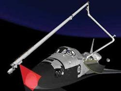
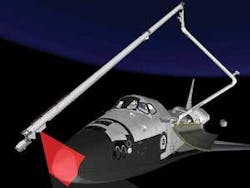
Mounted on an orbital replaceable mounting plate at the free end of the orbiter’s boom sensor system, the LCS examines damage-sensitive reinforced carbon-carbon leading-edge panels along the wings and nose and on the thermal-protection system on the shuttle’s underbelly (see Fig. 1). The LCS 3-D imaging and contour-mapping capability is also used as a confirmation and measurement tool when an area of interest is identified. Based on an autosynchronous scanning principle developed by the National Research Council of Canada, the camera system’s design provides submillimeter-precision 3-D measurement over a 30º × 30º field of view and can be operated up to 10 m away from the target object.
Triangulation methods
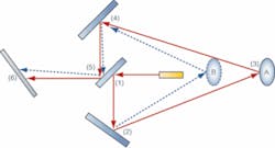
In basic triangulation methods, a beam is projected from one location and received at another. The distance between the emitter and detector and the beam angle determine the range to the target object. In an autosynchronous design, the separate projection and reception optics are “folded” into one single unit (see Fig. 2).
The LCS generates 3-D voxels by simultaneously sampling the angular position of the galvanometers and measuring the peak location and intensity on a SU256LX-1.7RT 256 × 1-pixel linear detector array from Sensors Unlimited. The indium gallium arsenide-based detector has selectable gain settings with a peak sensitivity around 1500 nm. The combined measurements of angles and laser peak position can be transformed into x, y, and z and intensity for every sampled location.
Regardless of lighting conditions, the camera system renders 3-D images that can be zoomed and tilted to reveal tiny defects. The system’s insensitivity to lighting conditions is crucial in space, where large contrasts between shaded and sun-exposed areas exist. Because of this, the laser wavelength used in the design was fixed at 1500 nm, a wavelength of relatively low intensity within the solar spectrum. Additionally, a narrow bandpass filter from CVI Laser Optics is located in front of the detector to filter solar background energy.
Operating Environment
The on-orbit environment is harsh and creates daunting technical design challenges. Temperatures can vary by as much as 80°C between sunrise and sunset during a 90-min diurnal cycle. The LCS must be able to operate within an environment as cold as −110°C and as warm as 25°C.
To do this, reflecting material was installed in the system enclosure’s external walls. This limits the temperature variation caused by sunlight. Radiators were mounted on the enclosure to allow the heat produced by the electronics to radiate out of the enclosure. Based on thermal analysis by Neptec scientists, Minco thermofoil heaters and thermostat were selected for use in the system. This same thermal analysis also determined the required radiated surface area to maintain the LCS components within their respective operating temperatures.
The camera system’s optical path requires precise alignment, and this must be preserved as the temperature changes. The optical subassemblies must sustain random vibrations that are inherent with the million pounds of lift-off thrust and turbulence during re-entry. To counteract the vibrations, the optical subassemblies are mounted on a plate composed of a rigid carbon laminate from ATK Space Systems, with a near-zero coefficient of thermal expansion. Selected for their strength and materials, the optical components are matched to provide thermal stability throughout the optical assembly.
The LCS is operated within low Earth orbit and is partially protected from radiation by the Van Allen belt, enabling the camera to be built with a mix of industrial-, military-, and space-grade components. Electronic components and circuit-card assemblies were tested at the Indiana University Cyclotron Facility to determine system tolerance to radiation. This made it possible to use some commercially available technology, while maintaining the robustness and integrity of the system.
Electronic control
Camera electronics comprised a power supply, a processor card, and a laser galvanometer controller card that contains a 1500-nm continuous-wave laser from Fitel and galvanometer control electronics. The laser galvanometer card interfaces with the processor card via programmable logic that monitors the operation of both the laser source and M2ST galvanometers from GSI Lumonics. There have been minor modifications made to the laser to meet aerospace requirements. The processor card also sets the laser-beam intensity and the galvanometer positions and samples the mirror angles. Galvanometer positions are accurately controlled by analog servo controllers that are adjusted for specific mirror inertia and galvanometer characteristics.
The processor card performs camera scan control, processes raw data into 3-D voxel format, runs diagnostics, and interfaces to a laptop computer located in the shuttle’s crew cabin. The camera system uses an embedded PowerPC running the Neutrino operating system from QNX. Two radiation hardened DSPs from Texas Instruments control the galvanometer positions and process data from the linear detector. A Xilinx Virtex2 Pro FPGA provides an interface to the three on-board processors, the detector, the laser and galvanometer controller card, and an Ethernet switch. The FPGA processes the raw data from the linear detector array.
As the photosensitive array generates data based on the returned light-intensity peaks associated with the scanned object, the FPGA extracts peak locations and transfers the data to one of the DSPs for further processing. Range information is then merged with the associated mirror angles and, once a scan line is complete, the data are transferred to the laptop via a KS8995MA Ethernet link from Micrel.
Astronauts must position the shuttle robotic arm and extension boom so that the LCS is facing the area of interest prior to performing a scan. Ground engineers provide a sequence of remote manipulator-system joint-angle commands to ensure that the arm and boom do not collide with the shuttle. Once the camera is positioned, an astronaut enters the scan parameters and initiates the scan using a laptop computer. After the scan is performed, the astronaut can assess scan quality and repeat the scan with different parameters, if required.
Displaying data
Once a scan has been completed, data are downlinked to the Mission Control Center at the Johnson Space Center. The scan is then analyzed for the presence of anomalies with the LCS analysis tool (LAT) developed by Neptec.
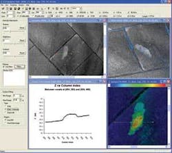
Using a camera-dependent calibration file, scan file voxels are converted from a spherical to an x, y, and z coordinate system. Data are then processed to detect and characterize the shuttle’s thermal protection system. Using the LAT, engineers can view data in 2- or 3-D, filter the data to reduce inherent measurement noise, and adjust image brightness and contrast. For anomaly characterization, the LAT allows operators to take on-screen measurements and provide graphical tools for data visualization (see Fig. 3).
By exporting the data to standard 3-D point-cloud file formats, information may be further analyzed using other third-party products, such as those from InnovMetric Software, to make volumetric measurements. Once the damage is characterized, the information is provided to NASA engineers and used in thermal-analysis software to determine if the damage poses any threat during shuttle re-entry.
The STS-114 mission proved the robustness, reliability, and integrity of the LCS technology, not only in the harsh low-Earth-orbit environment, but in its ability to visually comprehend any threat from damage incurred to the shuttle’s thermal protection system.
Stéphane Gagnon is systems and electrical engineer at Neptec Design Group (Ottawa, ON, Canada; www.neptec.com).
Company Info
ATK Space Systems
San Diego, CA, USA
www.atk.com
CVI Laser Optics
Albuquerque, NM, USA
www.cvilaser.com
Fitel
Peachtree City, GA, USA
www.fitel.com
GSI Lumonics
Wilmington, MA, USA
www.gsilumonics.com
Indiana University Cyclotron Facility
Bloomington, IN, USA
www.iucf.indiana.edu
InnovMetric Software
Sainte-Foy, QC, Canada
www.innovmetric.com
Micrel
San Jose, CA, USA
www.micrel.com
Minco
Minneapolis, MN, USA
www.minco.com
National Research Council of Canada
Ottawa, ON, Canada
www.nrc-cnrc.gc.ca
Neptec Design Group
Ottawa, ON, Canada
www.neptec.com
QNX
Ottawa, ON, Canada
www.qnx.com
Sensors Unlimited
Princeton, NJ, USA
www.sensorsinc.com
Texas Instruments
Dallas, TX, USA
www.ti.com
Xilinx
San Jose, CA, USA
www.xilinx.com


