Custom hardware boosts medical scanning speed and imaging
Custom hardware boosts medical scanning speed and imaging
R. Winn Hardin
Contributing Editor
Computed-tomography (CT) scanning was initially developed in England in the mid-1970s by Sir Geoffrey Hounsfield. With the evolution of computer technology and improved detector assemblies and x-ray tubes, human-body scanning has been steadily improved so that now several manufacturers produce CT systems. Indeed, CT scanners are widely used by hospitals and medical facilities worldwide. In the design of its LightSpeed CT system, for example, GE Medical Systems (Waukesha, WI) has upgraded its original CT design, with which four x-ray transmission intensity profiles per target slice can be collected while simultaneously increasing the number of slices per scan.
Whereas additional data generates more detailed two-dimensional (2-D) images and three-dimensional (3-D) reconstructed models, these data can also overburden the associated image-processing system. As a result, GE has developed a computer architecture consisting of a proprietary CT reconstruction engine with two digital-signal-processing (DSP) boards, an SGI (Mountain View, CA) O2 workstation that performs as a system controller, and an SGI Octane workstation (see Fig. 1).
Inside images
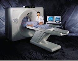
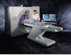
During a LightSpeed system scan, an x-ray source, located within a large circulatory gantry, moves around a patient lying horizontally on a sliding table. While keeping the patient in the middle of the doughnut-shaped gantry, detector assemblies in the gantry placed opposite the x-ray source collect the x-ray transmission levels across a given patient area or slices (between 4 x 1.25 mm and 4 x 5.0 mm per rotation), depending on the system slice-scan setting.
The electronics subsystem in the gantry digitizes the analog signals from the detectors into 20-bit digital data, which are then transmitted along a slip-ring assembly to a fiberoptic cable that leads to the GEMS-CT proprietary reconstruction engine.
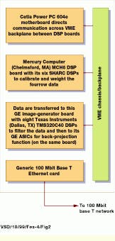
A GE-designed PCI card channels data from the fiberoptic input to an SGI O2 workstation`s disk-storage memory. The stored data are transferred over a 100BaseT Ethernet connection to a VME chassis controlled by a 604e PowerPC motherboard from Cetia (Toulon, France). This motherboard also controls the Mercury Computer (Chelmsford, MA) MCH6 DSP board and its six SHARC DSPs to calibrate and weight the four-row detector data. In turn, these data are transferred to a GE image-generator board, which contains eight Texas Instruments (Dallas, TX) TMS320C40 DSPs, to filter the data and then deliver the results to special GE ASICs for back-projection displays.
By activating four detector rows at a time and using a detector assembly with 888 channels per row, a number based on the desired resolution and scanner field of view, the CT system can adjust the number of detector slices collected during one x-ray-source rotation. This approach captures more of the x-ray output, which quadruples detector-tube efficiency before allowing the x-ray source to cool. (X-rays are created by bombarding a target with an electron stream and therefore generating heat.)
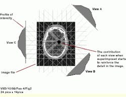
During a CT scan of a human head, for example, the x-ray source and the detectors both circle the head and collect data at 1000 points along each full rotation. At each viewpoint, the four active detector rows collect slightly different data for the transmitted x-rays. The digital data from each view are sent to the MCH6 DSP board. Here, algorithms written in C and hand-optimized code direct the calibration of the detectors, weigh the profile-specific data, and convert the data to an intensity measurement using negative logarithmic functions (see Fig. 2).
Because the weighting mechanism is proprietary, says Bob Senzig, systems engineering manager at GE Medical Systems, the process is complicated. "Each CT manufacturer has its own way of doing this," he adds. "This goes to the heart of the four-detector system that makes LightSpeed image quality what it is." After the detector data have been processed and weighted, the processed viewing data are fed from the DSP card across the VME backplane and into the image generator board for filtering and back-projection.
Back-projection is common in nearly all CT systems; it involves the conversion of x-ray intensity values to a cross-sectional image. The produced image contains 12 bits of gray-scale information, while the remaining eight bits from the original data set contain patient, spatial, and protocol information. The back-projection process translates floating-point input data into integer output data. As each scan-slice is completed, it is moved along with scan-location data into the SGI Octane Single/Dual R12K 270/300-MHz host computer by the PowerPC motherboard. There, resident software based on the LightSpeed Visual Tool Kit and running on the SGI Octane Workstation builds a 3-D model by combining 2-D images into a 3-D scalar field; slice widths run from 1.25 to 5.0 mm. Overlap is defined by the system operator prior to the scan. The scalar field model, also known as a vector linear grid, is composed of millions of volume elements (voxels), which represent CT density data in Hounsfield units.
The 3-D reconstructed image is stored in the workstation`s RAM during manipulation and viewing on dual, color, medical-imaging monitors. While one monitor displays the 2-D/3-D images, the other monitor shows the operator set protocol (for example, head scan, slice widths, and other imaging information). The CT, 2-D, and 3-D data also can be transferred to digital storage in a medical or hospital Picture Archiving Communication System or in another workstation using the Digital Imaging and Communications in Medicine image format standard.
MIPs and MPRs
As image data become available, the LightSpeed system creates what GE calls "virtual space," which contains the 3-D model, camera, and light source. Says Senzig, "The virtual camera is the point of view of the observer in 3-D space. The virtual light source can be placed anywhere around the virtual object." Placement of the camera and light source are dictated by the system operator, depending on whether a radiologist needs to view the human head, spine, or internal organs.
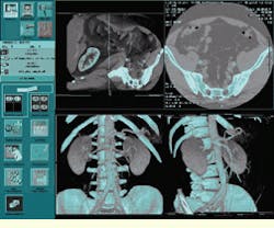
A maximum intensity projection (MIP) is a system-operator-requested function that highlights a specific area inside the human body, such as dye in a blood vessel. During operation, the MIP operation casts virtual rays through a certain spatial volume to produce a projected image. Each ray represents the projection of a portion of the volume onto a single pixel in the projected image. The system operator defines the origin of the ray and the direction through the object. Then, the MIP algorithm is activated to sample the voxels along the ray and store the highest intensity value encountered in the associated pixel. The result is a clear differentiation of an internal object, such as a chemically dyed blood vessel, tumor, or bone. Once the object area is highlighted, it can be isolated from the rest of the 3-D data and moved, manipulated, or viewed from any location in 3-D space (see Fig. 3).
"Some radiologists prefer MIP because it uses the original data, and they like looking at the original CT numbers without much processing," explains Senzig. "So for applications such as visualizing a contrast agent in a vessel or artery, it`s easy to see with MIP. However, MIP is not especially useful for visualizing an organ such as the liver."
By extending the operator-defined ray into a plane, the radiologist can use a multiple-planar-reformation (MPR) function to resample the original volume and display it as a longitudinal cut through the entire 3-D model rather than as an orthogonal or axial image. "When you look at the axial slices you see a vertebra, cartilage, then another disk. But if you look at MPR, you can see the profile of the entire spine," says Senzig.
Rendering and flybys
In surface rendering, the system operator defines the positions of the volume and the camera and also the placement of the virtual light source. The SGI Octane workstation then traces the rays through the volume and highlights the first opaque voxel encountered by ignoring all the data behind it. The surface point encountered is then shaded using the light-source model. The resulting intensity information is stored in the pixel that represents the path of the ray through that planar surface. Once a particular surface is defined, such as a bone, tumor, or artery, the LightSpeed system can calculate the area of the surface and the volume using standard measurement techniques.
Surface rendering is a subset of the volume-rendering function. Similar to surface rendering, the system operator defines the view of the 3-D model. However, with volume rendering, the system operator can also set opacity values for objects in the model, allowing the radiologist to see through bone and skin to the tissue underneath. This rendering allows radiologists to see subtle variations in CT densities, such as those found along a small blood vessel below a surface. It can also highlight various objects within the 3-D model by mapping CT density measurements to the color of different tissues.
An additional 3-D "navigator" feature of the Advantage Workstation allows the radiologist to virtually "fly" through internal structures. By isolating objects such as the spine or an artery by means of the available CT imaging techniques, the system operator can use the 3-D navigator to quickly shift through the 2-D slices that comprise the isolated object.
Although radiologists generally view individual scanned slices to make a diagnosis, the 3-D model is crucial to easy manipulation of the hundreds of slices that make up one CT scan. According to Senzig, a large part of making the increased data set manageable is the SGI computers` graphic capabilities. He says, "Today, skilled technicians take up to one hour to make one 3-D model. We`re going to be cutting that down to a few minutes."
Senzig reports that GE Medical Systems will continue to improve the speed and performance of the LightSpeed CT system by optimizing code and hardware.
The latest GE Medical Systems CT scanners offer fast volume acquisition and viewing of hundreds of CT slices using either a dedicated Sun Microsystems computer in an Advantage Workstation or a SGI Octane computer as part of the GE LightSpeed system.
FIGURE 1. GE-designed PCI card channels data from the fiberoptic input to a SGI O2 workstation`s disk-storage memory. The stored data are transferred over a 100BaseT Ethernet connection to a VME chassis controlled by a Cetia 604e PowerPC motherboard. This motherboard also controls the Mercury MCH6 DSP board and its six SHARC DSPs to calibrate and weight the four-row detector data. In turn, these data are transferred to a GE image-generator board, which contains eight Texas Instruments TMS320C40 DSPs, to filter the data and then deliver the results to special GE ASICs for back-projection display.
FIGURE 2. Proprietary algorithms are used in the LightSpeed CT system to convert image data to a series of intensity measurements. After intensity values are computed, proprietary back-projection algorithms generate cross-sectional image data.
FIGURE 3. GE Medical Systems LightSpeed CT system provides radiologists with several views in addition to the original CT slices (top right), including volume renderings (bottom).
Company Information
Cetia
83078 Toulon Cedex 9, France
(33) 4 94 16 34 00
Fax: (33) 4 94 16 34 01
Web: www.cetia.com
GE Medical Systems
Waukesha, WI 53188
(414) 544-3011
Fax: (414) 544-3384
Web: www.ge.com/medical
Mercury Computer Systems
Chelmsford, MA 01824
(978) 256-1300
Fax: (978) 256-3599
Web: www.mc.com
SGI Inc.
Mountain View, CA 94039
(650) 960-1980
Fax: (650) 961-0595
Web: www.sgi.com
Sun Microsystems
Palo Alto, CA 94303
(650) 960-1300
Fax: (650) 969-9131
Web: www.sun.com
Texas Instruments
Dallas, TX 75266
(972) 995-2011
Web: www.ti.com
