Machine vision checks dialysis filters
Andrew Wilson, Editor, [email protected]
Patients with kidney failure often must undergo dialysis to clean wastes from the blood. To accomplish this, hospitals use dialyzers that remove blood from the patient, pump the blood through a dialysis filter, and return the cleaned blood to the patient. Because the filter performs many of the functions of the kidney, it is often referred to as an artificial kidney. Inside the filter, blood travels though many tiny tubes made up of hollow fibers. Because water and solutes can pass across the semi-permeable membrane between the blood and the fluid that surrounds the hollow fibers, any waste in the blood can be captured and drained.
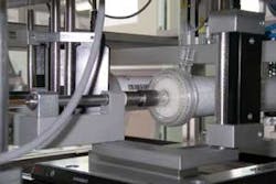
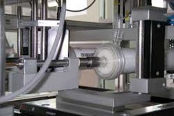
“When these filters are manufactured,” says Heiko Frohn, executive managing director of Vitronic (Wiesbaden, Germany; www.vitronic.de), “a cap must be placed at both ends of the filter that allows blood to flow in and out of the filter” (see figure). It is imperative that no dust or particles exist between the input and output faces of the caps and that no particles are present in the thread that attaches the cap to the filter. “If this were to occur,” says Frohn, “then particles might pass into the bloodstream of the patient.”
To ensure such particles do not exist, Frohn and his colleagues have developed an automated system that inspects both the input and output faces of the caps and the screw threads that are used to attach them to the filter. “One of the main difficulties in developing such an automated system,” says Frohn, “was choosing the correct type of lighting.” Because the caps are curved in nature and are partially transparent and partially reflecting, it is not easy to simultaneously illuminate all parts of the filter.” Although Frohn would not be more specific, he indicated that the final system did use a number of different techniques including a semi-diffused directed light and an LED lamp that sequentially illuminated the part.
To attain a high throughput rate of only a few seconds per part, the filters with caps were inspected in rotation. At each end of the filter, an A102f 1.4-Mpixel FireWire camera from Basler Vision Technologies (Ahrensburg, Germany; www.baslerweb.com) captures images of the assembled filter. “Because of the 12-bit, 1392 × 1040-pixel digital output of the camera,” says Frohn, “we could obtain high-resolution images with a high dynamic range.” This was especially useful because of the detail required in the inspection process.
To inspect for particles in the thread between the filter and cap, two VGA FireWire cameras, also from Basler, were mounted at 90° to the axis of the spindle. These were also interfaced to the systems host PC. “As the assembled filter spins, images are captured in segments of 30°,” says Frohn. Images from both ends of the filter and both ends of the thread are then transferred to the host PC for processing. Vitronic’s machine-vision software VINSPEC is then used to check and classify each of the filters according to the filter manufacturer’s specific criteria. This information can then be stored in a common database for further analysis.

