Plating manufacturer applies x-ray fluorescence testing for increased accuracy

Plating manufacturer applies x-ray fluorescence testing for increased accuracy
By John Haystead, Contributing Editor
Aplater and finisher of electronic components, Handy & Harman Electronics Materials (H&H; N. Attleboro, MA), produces a variety of products, ranging from LED display frames to microelectronic connectors and contacts. Many of the company`s production lines apply gold, silver, palladium, nickel, and copper-plating metals to parts of different configurations and shapes, and the company has chosen x-ray fluorescence techniques to continuously inspect and monitor the quality of its processes for more accuracy.
X-ray fluorescence (XRF) is a noncontact, nondestructive technique that measures elemental mass per unit area at microinch accuracies. When exposed to x-rays of a specific intensity, individual elements fluoresce at a rate proportional to their concentration. Therefore, XRF spectral analysis provides quantitative information about a material`s elemental composition and trace elements in its matrix. By using XRF, manufacturers can analyze the thickness of opaque or translucent materials in angstroms (10-10 m) to microns (10-6 m).
Production requirements
Handy & Harman`s plating process links individual stamped parts together as they pass along 70- to 100-ft plating lines. It uses four XRF300 x-ray fluorescent test instruments from Veeco Instruments/UPA Technology Division (Plainview, NY) to support all the production lines and perform more than 5600 inspections per week.
"Prior to using these systems," says Charlie Coffroth, H&H quality-control manager, "each sample was mounted in an acrylic housing and measured with a microscope. Because this could take three to four hours per sample, we could have produced $15,000 to $20,000 worth of bad product by then. Today, the same information can be obtained in ten seconds."
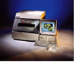
The XRF system consists of an x-ray source, detector, mounting stage, host computer, and spectrum-analysis software. Veeco`s Series 5000 machines use a Pentium PC with 32-Mbyte RAM, 1.6-Gbyte drive, CD-ROM, 14-in. SVGA monitor, and 3.5-in. floppy-disk drive (see Fig. 1). The system`s Xpert software runs under both DOS and Microsoft Windows.
To make a test, samples are first mounted on the mounting stage and placed in a test chamber. Before inspection, each metal and metal combination being measured are calibrated and compared to known values. System software then prompts the operator to input the metal being analyzed and subsequently loads the appropriate calibration tables.
Because the metallic areas to be measured can range from 3 to 40 mils square, the operator also must configure the beam size of the x-ray. Using the PC keyboard, the operator selects one of a series of pinhole apertures, or collimators. Although the size of the x-ray beam is equal to the diameter of the collimator, its size at the sample`s surface is a function of the distance between the collimator and the target. To properly focus the beam, a Class-II 0.1-mW laser located in the test chamber is used to measure this distance.
Because the products to be tested have complex shapes, the x-y-z movement of the stage plate must also be programmed. Interfaced via a control card to the PC, the motorized stage plate can be programmed to a 0.5-mm accuracy. A video camera and 3X relay-lens system, also mount ed in the test chamber, provides a live image of the sample as it is positioned. This video image is overlaid with a computer-generated reticule that highlights the area to be struck by the x-ray beam (see Fig. 2).
"On some jobs," says Coffroth, "it is not necessary to secure the part to the stage plate. Instead, it can be mounted in a small fixture and placed on the stage plate close to the location to be measured. The system`s software then prompts the operator to identify two points on the sample, from which the software extrapolates the configuration of the part and automatically moves the stage plate to the correct position for the collimator beam."
Coffroth has more than 100 different measurement methods and 500 stage-plate patterns programmed into the x-ray systems, all of which are stored on the system`s hard-disk drive. Coffroth says some programs can be performed in less than five minutes. "The system needs to know what metals it`s measuring and where to look. Then it automatically takes hundreds of readings with no further operator interaction," he adds.
Software makes it simple
"User-friendly software is everything," says Coffroth, "because, although the inspection tasks are technical, the system operators are not scientists." Although Xpert for Windows and Windows `95 versions are available, Coffroth prefers to run a DOS-based version of the system software. He also makes extensive use of the system`s "Surfer" 3-D surface plot and 2-D contour-mapping software. Once installed, this optional package from Golden Software (Golden, CO) can be accessed directly through Xpert (see Fig. 3).
Frank Reilly, Veeco`s director of sales and marketing, states, "Compared to DOS, the Windows software provides better graphical features and allows users to personalize and store their own interfaces, program video capture, and implement a fully compatible network capability." However, Reilly acknowledges that some users still prefer DOS and, therefore, provides both Windows and DOS-based software (see Fig. 4).
At its East Providence, RI, plant, Handy & Harman is running a Windows `95 version of Xpert on an XRF-5000 series machine. There, Coffroth says, as many as 80 plating lines will be installed.
Looking ahead
In the future, Coffroth wants to network his existing systems, but because the facility`s existing Ethernet network is running at capacity, this would require installing a new network and server. As an interim solution, Coffroth is looking at linking the machines through an additional computer.
Coffroth estimates his current XRF systems will fill the company`s inspection needs for at least another eight years before they become obsolete--an important factor in the equipment planning and selection process. "You can spend a million dollars for a better x-ray machine, but in this business $30,000 to $50,000 is hard to find. Even though these machines can save you $30,000 a day when they find a problem, it`s still difficult to justify the expense," explains Coffroth.
Using x-ray fluorescent test instruments, a vendor is measuring the thickness and composition of metal plating with higher precision.
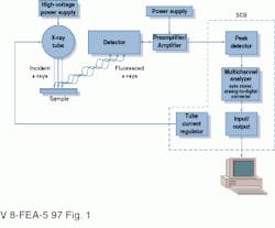
FIGURE 1. PC-based x-ray fluorescence measurement system consists of either a standard tungsten or high-performance molybdenum x-ray source, gas-flow detector, motorized mounting stage, host computer, and Windows or DOS-based spectrum-analysis software.
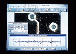
FIGURE 2. Xpert software includes linear, area-grid-scan, and random x, y, and¥programming modes. The full map provides an on-screen image of the entire stage with a computer-generated reticule displaying sample position and beam size of the currently selected collimator.
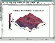
FIGURE 3. 3-D surface plot and 2-D contour mapping software prove useful as tools for evaluating plating operations.
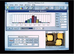
FIGURE 4. Together with a live view of the sample, Xpert for Windows software displays statistical information such as mean, standard deviation, range, capability indices, trendline analysis, x-bar and range charting, and histogram data in graphical forms.
Fundamentals of x-ray fluorescence
"In simplest terms, x-ray fluorescence (XRF) instruments are x-ray counting devices," says Marty Schreck, Veeco (Plainview, NY) applications engineer. As each fluoresced photon strikes the detector, its energy is converted into a proportional electrical signal with an amplitude proportional to its energy. The resulting signals are then sorted, saved, and counted.
Two types of x-ray detectors are generally used in XRF systems. In one type, Veeco`s XRF-series machines use gas-flow proportional counters that consist of an entry tube, amplifier, pre-amplifier, and system control board. The tube contains a coaxial wire filled with a combination of ionizing gases. A 2000-V potential between the outer shell of the tube and the positively charged wire filament creates an electric field. When the x-rays enter the tube through a beryllium window and ionize the gas, free electrons are drawn to the wire. On average, about 30 eV of energy are necessary to ionize one gas molecule.
In the solid-state or semiconductor detector type, x-rays impinge on a silicon/lithium semiconductor crystal, thereby creating a drift field and releasing electrons proportional to the incident energy. Semiconductor detectors give better resolution than gas-flow proportional counters because the number of electrons released per absorbed x-ray photon are higher.
Although solid-state detectors tend to have better sensitivity and are useful for examining thin coatings and minute trace analysis, they are more expensive. Still, due to their superior resolution and sensitivity, solid-state XRF detectors are being used to inspect semiconductor wafers, ball grid arrays, multichip modules, and surface-mounted devices. Veeco`s SEA-5000 Micro x-ray fluorescence instruments verify metallic and dielectric thin-film thickness and composition, measure microcontamination, and detect poor deposition processes. The instruments can also measure the thickness and composition of up to five layers in a matrix of 30 elements on wafer edges, scribe lines, and test pads.
Once generated, electron charges are shaped and amplified before being digitized by an analog-to-digital converter board that changes the signals at 50,000 counts/s. "We`re constantly looking at ways to increase the speed of this conversion to increase the detector`s sensitivity," says Reilly.
After conversion, the digital signals are analyzed by the PC-based multichannel analyzer. There, each pulse is sorted by energy level and stored in one of the analyzer`s 1024 memory locations, or channels. The number of pulses in each channel are then counted and thickness and composition of the material determined.
J. H.