Choosing optics for machine vision
The task of selecting the proper optics for a machine-vision application is eased by matching key design parameters to various types of lenses.
By Andrew Wilson,Editor
Apart from lighting considerations, correct optics contribute greatly to the proper performance of a machine-vision system. Moreover, with an increasing number of solid-state cameras becoming available, choosing the optics for a particular imaging application has become a challenging task. Fortunately, various types of lenses are currently offered for systems developers, including micro, standard, zoom, and telecentric lenses, that can be implemented for specific applications.
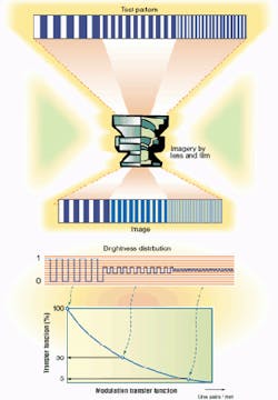
FIGURE 1. A key optical-system design parameter, the modulation transfer function, measures the ability of a lens to transfer contrast from the object to the camera sensor. The resulting curve is graphed with the percentage of contrast versus image resolution. (Courtesy Schneider Optics)
In choosing optics for an imaging system, several key parameters must be addressed. They include the minimum feature size to be detected, the field of view (FOV) or the area to be imaged, the distance from the camera sensor to the object, the type of image sensor used, and the required depth of field. Proven optics and lens formulas can be used to determine the needed parameters of the lens.
In C-mount lens designs, for example, the detector is placed 0.690-in. behind the camera's front flange. Accordingly, when the focus ring is set to infinity, the detector is at the back focus of the lens. This approach simplifies the process of distance calculations, especially when determining the length of an extension or spacer between the camera and lens.
Minimum feature size
Before a lens is specified, it is crucial for the developer to determine the minimum feature size that must be recognized by the imaging system. This procedure generally involves the use of test charts such as the US Air Force 1951 three-bar resolving-power test chart. Such charts generally consist of alternating dark and bright bars of the same width and of varying patterns of smaller bars and spaces.
In such patterns, the highest resolution is calculated as the number of line pairs per millimeter that are barely recognizable. However, the limit of resolution alone is not an adequate measure of image sharpness—the modulation with which the pattern is reproduced must also be considered (see Fig. 1). From experiments, the maximum resolution attainable from film with the highest-resolution optics is about 75 lp/mm. By using today's high-resolution 2k x 2k-pixel and greater image sensors, this maximum resolution is approximately 40 lp/mm.
"Determining minimum feature sizes for an imaging system can be tricky, especially when using coherent lighting, because diffractive effects come into play," says Jonathan Kane, director of research and development at Computer Optics (Hudson, NH). "One rule of thumb is to use an acquisition system that is at least a factor of two better resolution then your minimum feature size. For coherent light, allow at least three orders or up to a factor of five more system resolution than required by your minimum feature size," he notes.
Sensor choices
After the minimum feature size of the desired image is determined, the next step is to determine the type of camera needed. Present solid-state cameras are supplied with different image sensor chip sizes, such as 1/4, 1/3, 1/2, 2/3, and 1 in., all of which maintain a standard 4:3 (horizontal to vertical) aspect ratio (see Fig. 2). To calculate the lens magnification required, developers divide the minimum resolvable image size by the pixel size.
If the smallest feature size to be imaged is 100 µm, for example, and each element in the CCD array is 10 µm wide, the magnification required is approximately 10X. "Often you have to decide which is more important, resolution or overall object size. This trade-off is called the "space bandwidth product," and it is always something the optical designer has to balance," says Kane.
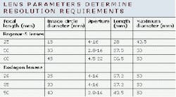
To measure the quality of a certain length of material, a linescan camera may be required. If, for example, the linescan sensor consists of 2048 pixels, each of which is 14 µm in width, then its length is 28.7 mm. If the length of the material to be measured has a width of 300 mm, then the needed lens magnification is 28.7/300 = 0.096. A magnification of 0.1 allows a number of lenses with a focal length from 28 to 105 mm to be used. But, to choose the correct lens for this application, the image circle that encompasses the whole imaging area must exceed the sensor's 28.7-mm length. The table below shows that the image circles of the Rodenstock Precision Optics (Rockford, IL) Rogonar-S 25 and Rodagon 28 lenses are too small. The image circle of the Rodagon 35 almost equals the length of the sensor but should still be avoided.
Under these design constraints, a focal length of 40 to 105 mm can be chosen depending upon the desired front-working distance. For example, the front-working distance of a 40-mm lens at a magnification of 0.1 is 400 mm; the corresponding working distance of the 105-mm lens is 1050 mm.
After the lens magnification (M) is determined, the lens' focal length can be calculated by dividing the total distance from the image plane by (M + 2 + 1/M). If, for example, the object is 300 mm away, then the focal length of a lens with a 10X magnification is 300/(10 + 2 + 0.1), or approximately 25 mm.
When used with the same focal-length lens, detectors of different sizes will each yield a different field of view. Lenses designed for a large image sensor will work on a new, smaller size camera. However, if a lens designed for a smaller format image sensor, such as 1/3 in., is placed on a larger one, such as 2/3 in., the displayed image will have dark corners.
Focal lengths and apertures
Because focal length is directly related to both the object-to-image distance and the magnification, developers can trade off one with the other in considering which type of lens to use. In machine-vision systems, lenses are generally classified as standard, wide angle, telephoto, zoom, and telecentric, each of which features different focal lengths and operational characteristics.
Standard lenses feature a 50-mm focal length, and their picture angle most closely approximates the view of a human eye. Because the maximum aperture or f-number of these lenses is generally small, such lenses can be used with high-speed camera shuttering. With a focal length of less than 50 mm, wide-angle lenses capture wider images than those of the human eye. And, although more of the area to be imaged appears than with a 50-mm lens, each part of the image is smaller. Telephoto lenses, which have a focal length greater than 50 mm, bring remote objects into view but decrease the overall perspective and reduce the depth of field of the imaging system.
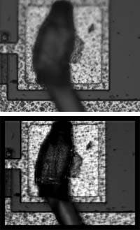
FIGURE 3. Two images of a semiconductor have been taken with a Zeiss Axioplan microscope; a 20X, NA = 0.5, Epiplan objective; and a Cooke SensiCam digital camera. Although the traditional image (left ) offers a clear picture of the surface of this semiconductor IC, the leads attached to the edges of the IC quickly extend out of focus. A wavefront-coded image (right) shows that the semiconductor IC and its leads are all sharply focused with no loss of lateral resolution.
Conventional lenses view objects at different angles across the field of view. This characteristic changes the viewing perspective and can distort the size and shape of the object, making it difficult to view features accurately. Magnification in telecentric lenses, unlike conventional lenses, is independent of working distance. And magnification remains constant regardless of how close or far away an object is from the camera. This property reduces magnification errors and extends the gauging of depths of field. Conventional lenses, however, view objects that are closer to the camera as larger than objects that are farther away.
Just as the object-to-image distance directly relates to the focal length of the imaging system, the maximum aperture, or f-number, of a lens is characterized by the focal length of the lens divided by the effective aperture. Because faster shutter speeds are often used in machine-vision applications, a small f-number lens effectively reduces the likelihood of camera shake, which blurs images. When a subject is illuminated under identical brightness conditions, smaller f-numbered (maximum aperture) lenses result in faster shutter speeds.
Depth of field
The depth of field of an imaging system is that distance of the object space in which objects are considered to be in focus. Accordingly, extending the depth of field of an imaging system will extend the distance over which objects are in focus. Traditionally, increasing the depth of field is performed by decreasing the size of, or stopping down, the aperture of the lens. This method, however, reduces the amount of gathered light. For example, stopping down a lens by one f-stop reduces the amount of light passing through the lens by a factor of two. A typical high-speed imaging application may require the aperture to be stopped down to the f/30 range, necessitating the addition of higher illumination to obtain useful data.
To extend the depth of field by ten or more times without stopping down the aperture or increasing illumination, CDM Optics (Boulder, CO) has developed a method called Wavefront Coding. This method uses generalized aspheric optics to encode images that are invariant to mis-focus and digital signal processing to decode the images. Using this method, an f/2 system can produce a depth of field equivalent to an f/20 system while retaining the light gathering ability and the spatial resolution of the f/2 system.
An extended depth of field by means of wavefront coding is realized using modified optics and signal processing to obtain a larger depth of field. Because the wavefront-coded phase mask is simply an aspheric optical surface, no optical power is sacrificed in the process. The company expects to introduce a development system using this technology targeted at semiconductor inspection. This high-magnification development system will consist of a modified 10X long working range objective, a CDM Optics proprietary optical element inserted in the back aperture, an extension tube, an 8- or 10-bit digital camera, a frame grabber, and customized software. Initially, the system will be targeted at semiconductor inspection (see Fig. 3).
Whereas other design factors such as lighting, image digitization, and processing also can be used to optimize the performance of an imaging system, choosing the proper optics and thus obtaining the best image is of primary importance in developing machine-vision systems. To assist developers, several manufacturers of lenses and optical systems are using their Web sites to present tutorials and lens-selection guides. These Web sites contain reference charts, product information, helpful hints, and applications information to provide a thorough understanding of optical technologies.
Company InformationDue to space limitations, this Product Focus article does not include all of the manufacturers of the described product category. For information on other suppliers of lenses, see the 2000 Vision Systems Design Buyers Guide (Vision Systems Design, Feb. 2000, p. 47, Lenses).CDM Optics
Boulder, CO 80303
Web: www.cdmoptics.com
Computer Optics
Hudson, NH 03051
Web: www.computeroptics.com
Edmund Industrial Optics
Barrington, NJ 08007
Web: www.edmundoptics.com
Light Works
Toledo, OH 43624
Web: www.lw4u.com
Melles Griot
Rochester, NY 14620
Web: www.mellesgriot.com
Moritex
San Diego, CA 92121
Web: www.moritexusa.com
Navitar
Rochester, NY 14623
Web: www.navitar.com
Rodenstock Precision Optics
Rockford, IL 61109
Web: www.rodenstockoptics.com
Schneider Optics
Hauppauge, NY 11788
Web: www.schneideroptics.com
The Imaging Source
Charlotte, NC 28204
Web: www.theimagingsource.com


