Autostereoscopic system delivers 3-D images using cylindrical lenses
Incorporating a lenticular screen, an autostereoscopic system lets a viewer see three-dimensional images without the use of glasses.
By Andrew Wilson, Editor at LargeCurrent three-dimensional (3-D) display devices use various methods to produce the illusion of 3-D space. While some systems require the use of special eyeglasses or displays mounted directly in front of both eyes, autostereoscopic systems avoid the use of such devices and attempt to cast different images in both eyes of the viewer automatically.

"Autostereoscopic displays present a spatial image to a viewer without the use of glasses, goggles, or other viewing aids," says Michael Halle of the Surgical Planning Laboratory at the Department of Radiology of Brigham and Women's Hospital (Boston, MA). "These displays are appealing because they offer the best approximation to the optical characteristics of real objects. However, there is much misinformation given out by those seeking to oversell the capabilities of such technology," he says.
According to Halle, autostereoscopic displays can be classified into re-imaging, volumetric, and parallax types. Whereas re-imaging displays capture and reradiate the light from a 3-D object, volumetric displays span a volume of space and illuminate individual segments. Parallax displays use lenticular panoramagrams along with two-dimensional (2-D) display devices such as cathode-ray tubes (CRTs) or liquid-crystal displays (LCDs) to produce 3-D images.
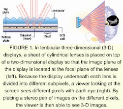
In these displays, a sheet of cylindrical lenses is placed on top of a CRT or LCD so that the image plane of the display is located at the focal plane of the lenses. Because the LCD underneath each lens is divided into different subpixels, a viewer looking at the screen sees different pixels. By placing a stereo pair of images on different pixels, the viewer is then able to see 3-D images (see Fig. 1).
Head tracking
Currently, several manufacturers offer prototype displays that use this type of technology to derive 3-D images. They include Dimension Technologies (Rochester, NY), The Dresden Technical University (Dresden, Germany), Heinrich-Hertz Institute (Berlin, Germany), Philips Research Labs (Redhill, Surrey, England), and Sanyo Electric (Tokyo, Japan). The initial versions of these systems required the viewer to remain in a fixed position to observe the 3-D image. To ease that burden, many vendors are now incorporating head-tracking devices into their systems, permitting the viewer to maneuver around the display monitor. These head-tracking systems automatically sense the viewer's head position and change either the LCD or the lenticular array to compensate for motion.
In the D4D system developed at The Dresden Technical University, the LCD display simultaneously shows right and left stereoscopic half-images in alternating columns. To ensure that the viewer's left eye sees the even-numbered columns and the right eye sees the odd-numbered columns, an image splitter is placed in front of the LCD. During operation, light passing through the odd-numbered columns of the LCD is deflected toward the right eye; light from the even-numbered columns goes toward the left eye.
To track the viewer's lateral head movement, the viewer's position is monitored by a proprietary camera-based eye finder. Results from the tracking operation are used to shift the half-images electronically or to shift the prism mask for correct deflection of the light beams.
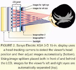
The XGA 3-D 15-in. display from Sanyo Electric also uses motion tracking to detect the viewer's head position and it adjusts images automatically for the viewer's left and right eyes. Using the company's proprietary double-image splitter technology, image splitters are placed in front of and behind the LCD panel to separate the images for the viewer's left and right eyes (see Fig. 2).
Eliminating tracking
A major limitation of autostereoscopic systems that use head-tracking techniques is that only one viewer can use the system at a time. To overcome this limitation, researchers at Philips Research Labs have developed an autostereoscopic, 3-D LCD that allows unrestricted viewer head movement without the use of head-tracking devices.
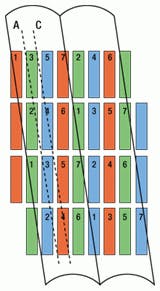
FIGURE 3. In the Philips 3-D LCD, a lenticular screen is placed over the LCD at a slanted orientation to intersperse odd- and even-numbered views. As the viewer's head moves with one eye closed between positions corresponding to slanted-lines A and C, a viewing changeover takes place in which viewer-zone 3 fades out and viewer-zone 4 fades in. This fading effect achieves the illusion of a solid object being seen by the viewer rather than a succession of discrete (flipping) views.
To create the 3-D illusion without head-tracking devices, Philips has developed a seven-view 3-D LCD system that creates odd-numbered views using a lens and even-numbered views using a second lens (see Fig. 3). When the viewer's head moves laterally to the right, for example, the viewer's left-eye observation zone changes from 5 to 4 and, simultaneously, the viewer's right-eye observation zone changes from 3 to 2. In this way, both eyes still see different images. This display system produces a succession of viewing zones in which their numbers are continuously repeated with the lateral movement of the viewer's head (for example, zones 3, 4, 5, 6, 7, 1, 2, 3, 4, 5, 6, 7, 1, 2), thereby allowing the display to be seen by multiple viewers simultaneously.
To intersperse the odd- and even-numbered views, a lenticular screen is placed over the LCD at a slanted orientation. Because the LCD is located at the focal plane of the lenticular screen, all the numbered zones on slanted-line A are seen simultaneously by one eye of the viewer at one specific horizontal viewing angle. Under each lenticular, the pixels of viewer zone 3 are positioned on alternate rows. Slanted-line C represents another position in which only pixels from viewer zone 4 can be seen. Therefore, as the viewer's head moves with one eye closed between zones corresponding to lines A and C, a changeover occurs in which viewer-zone 3 fades out and zone 4 fades in. This fading process achieves the viewer's illusion of seeing a solid object rather than a succession of discrete (flipping) views.
Medical applications
In microscopy and medical image-processing applications, rendered 3-D images of human cells or anatomy provide researchers with a comprehensive understanding of displayed data. To render these images, several off-the-shelf image-processing software packages are available (see Vision Systems Design, Dec. 1997, p. 30). Usually these images are displayed in two dimensions and rotated and tilted to provide the viewer with different views. Now, with autostereoscopic displays available as prototypes, researchers are incorporating these devices into medical imaging systems.
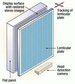
FIGURE 4. In a collaborative effort, Carl Zeiss and the Heinrich-Hertz Institute have developed a 14-in. 3-D TFT-LCD monitor for displaying medical images (top). To allow viewer head movement, the display system incorporates a head-detecting video camera that shifts a lenticular plate in two directions (bottom). This setup allows the viewer's eyes to move over a viewing area of 15 x 15 cm.
In a cooperative development between Zeiss (Oberkochen, Germany) and the Heinrich-Hertz Institute, for example, a 14-in., 3-D TFT-LCD monitor has been developed for medical applications. Using a 768 x 1024-pixel display and a lenticular plate, the monitor can display 3-D images at a viewing distance of 60 cm. To allow viewer head movement, the monitoring system incorporates a head-detecting video camera that shifts the lenticular plate in two directions. This design permits the viewer to move over an area of 15 x 15 cm (see Fig. 4).
Autostereoscopic systems also are providing useful information for diagnosing glaucoma-an eye disease. At present, ophthalmologists are using 3-D data from retinal tomographs to observe the topography of the retinal surface and the optic nervehead. Topography data are used to characterize the morphology of the optic nerve head and its internal excavation. To evaluate the progress of glaucoma, the contour of the optic nervehead is manually outlined and an excavation border is derived.
Ophthalmologists also add the topography image to a reflectivity image to draw this contour (see Fig. 5). However, because obtaining the correct spatial impression of the papilla morphology from these 2-D images is a complicated process, the accuracies of the resulting measurements and the derived evaluations are reduced.
To overcome these limitations, researchers at The Dresden University of Technology have coupled the 3-D data with an autostereoscopic display to generate a 3-D image of the optic nervehead without the need for special glasses or other hardware. Using this approach, ophthalmologists do not need to correlate information from two independent images because they can be overlaid as a 3-D impression that includes reflective values.
FIGURE 5. Ophthalmologists use topography images with reflectivity images to draw a contour of the optic nervehead (top left). However, because it is difficult to obtain the correct spatial impression of the papilla morphology from these 2-D images (top right), the accuracies of the resulting measurements and the derived evaluations are reduced. To overcome this problem, researchers at The Dresden University of Technology have coupled these 3-D data with an autostereoscopic display to generate a 3-D image of the optic nervehead (bottom).
"Used in a clinical environment, the 3-D presentation on the autostereoscopic display represents an enormous improvement over the accuracy of manual contour definition," says Hans-Juergen Malig of Dresden Informatik (Dresden, Germany), one of the partners that developed the visualization software and the autostereoscopic display. "Because it is feasible to make the pictures rotate around their axes, new insights to the morphology of the optic nervehead can be obtained," he adds. Combining topography and reflectivity data in one view makes it easier to draw the papilla contour. "And, a computer-aided drawing of the papilla contour, which can be corrected by the ophthalmologist, makes morphology measurements easier and more reproducible glaucoma diagnosis," Malig notes.
Software support
To display 3-D images, software packages must be used that match the specific autostereoscopic display. For this reason, manufacturers of lenticular 3-D displays offer their own or third-party software to render 3-D images on their displays. For example, when developing 3-D images using the Virtual Window displays from Dimension Technologies (Rochester, NY), the Kinetix 3D Studio MAX-modeling package available from Discreet (Montreal, Quebec, Canada) can be used. During processing, image files must first be translated into Microsoft's DirectX file format by a translation package such as PolyTrans or NuGraf from Okino Computer Graphics (Mississauga, Ont., Canada).
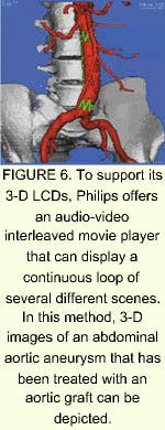
Philips also offers software packages to support its 3-D LCD displays, such as Octopus. This Windows-based multiview editor provides two independent windows: one to open different images in PaintShop Pro and the other to simultaneously visualize 3-D images. Another software display package, DemoAvi, is an audio-video interleaved movie player that can show movies frame by frame. According to Philips, the software was written to supply a 3-D LCD display with a continuous loop of several different scenes, including 3-D images of an abdominal aortic aneurysm that has been treated with an aortic graft (see Fig. 6).
Prototypes of autostereoscopic displays are now available, and they are finding use in numerous research applications. However, because such displays must provide the viewer with different views to generate the illusion of depth, the resolution of each image per view is reduced. For example, in the Philips 3-D LCD seven-view monitor, the 1024 x 768-pixel XGA display provides a color resolution per view of 438 x 256 pixels. To attain the resolution and perhaps the number of views required to meet the needs of many 3-D applications, larger LCDs need to be fabricated. When this happens, multiview, 3-D LCDs will begin to appear on the desktop.
Company Information
Brigham and Women's Hospital Surgical Planning Laboratory
Boston, MA 02115
Web: www.bwh.partners.org
D4D Product Sales
Dresden, Germany
E-mail: [email protected]
Dimension Technologies
Rochester, NY 14611
Web: www.dti3d.com
Discreet
Montreal, QC, Canada H3C 2L7
Web: www.discreet.com
Dresden Informatik
Dresden, Germany
E-mail: [email protected]
The Dresden University of Technology
Dresden, Germany
Web: www.inf.tudresden.de/D4D/index.htm
Heinrich-Hertz Institute
Berlin, Germany
Web: www.hhi.de
Okino Computer Graphics
Mississauga, Canada L4V 1T8
Web: www.okino.com
Philips Research Labs
Redhill, Surrey, England
Web: www.research.philips.com/generalinfo/special/3dlcd/
Sanyo Electric Co.
Tokyo, Japan
Web: www.sanyo.com
Volume Graphics
Heidelberg, Germany
Web: www.volumegraphics.com
Carl Zeiss
Oberkochen, Germany
Web: www.zeiss.de