Camera interfaces vie for vision applications
By Andrew Wilson,Editor
Confronted by an array of camera interfaces, systems integrators must carefully match the attributes and limitations of each standard to their application.
Deciding on which camera to use for a specific machine-vision or image-processing application requires both an understanding of camera specifications and of how cameras are interfaced to host computers. Whereas low-frame-rate cooled CCD cameras prove most useful in applications such as astronomy and bioanalysis, high-frame-rate or linescan cameras may be required for machine-vision applications.
Cameras also interface to host computers in a number of different ways. Indeed, today's designers of machine-vision and image-processing systems are confronted with several camera-interface choices. These range from bus-based topologies such as IEEE-1394 (or FireWire) and USB 2 to single-link implementations such as RS-644 and Camera Link. In choosing the proper interface, designers must be aware of the different adapters, cable lengths, speeds, and prices involved in implementing each standard. To determine which interface best suits a machine-vision application, systems developers must carefully consider the benefits and limitations offered by each approach.
Bus-based topologies
Developed primarily to serve the consumer-electronics industry, the IEEE-1394 and USB interfaces and their succeeding generations are primarily plug-and-play bus architectures. Designed to leverage existing operating systems, IEEE-1394 and USB are serial interfaces that allow devices from different vendors to operate in an open architecture. Like most serial buses, these protocols are designed to accommodate short-distance communications of approximately 5 m (see table on p. 49). However, in both protocols, these distances can be overcome by using a number of hubs and repeaters in a network manner similar to Ethernet.
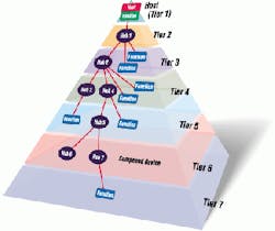
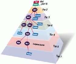
FIGURE 1. Due to constraints on hub and cable propagation times in the USB-2 interface standard, a maximum of seven tiers is allowed. Within these tiers a maximum of five nonroot hubs can be supported in a communications path between the host and any connected peripheral device (Figure courtesy USB Implementers Forum).
Originally developed in 1995 by Compaq, Intel, Microsoft, and others, the original 12-Mbit/s USB uses the host PC system's software to manage the dynamic attachment and detachment of peripherals such as cameras. By assigning a unique address to each camera, the host PC can initiate transactions between specific peripherals and accept each camera's response. To add more peripherals, up to five levels of hubs can be cascaded and operated as bidirectional repeaters between the cameras and the host.
The latest USB-2 version connects USB devices with the USB host at data rates to 480 Mbits/s. In operation, USB-2 hubs can accept high-speed transactions up to 480 Mbits/s and can be connected to both USB-2 and USB peripherals. This data-rate matching requires increased hub complexity and temporary data buffering. Due to the timing constraints for hub and cable-propagation times, a maximum of seven tiers is allowed (see Fig. 1). Within these tiers, a maximum of five nonroot hubs can be supported in a communications path between the host and any connected device.
Like USB, the original IEEE-1394 standard operates over short distances and low data rates. The IEEE-1394b version was recently released to overcome these difficulties. Because IEEE-1394b is also a serial bus, peripherals such as cameras can be configured by using hubs in a manner similar to that used for USB. To increase the speed of the bus and at the same time increase distance, IEEE-1394b abandons the simple data-strobe coding used in its predecessor for a dc-balanced, modified 8B10B data-coding scheme, similar to that used in Fibre Channel and Gigabit Ethernet. In every hardware implementation, however, IEEE-1394b devices can select between data-strobe coding and 8B10B coding, making IEEE-1394b device-compatible with those peripherals that comply with the IEEE-1394a standard.
Asynchronous and isochronous
In both the USB and IEEE-1394b standards, arbitration methods allow peripherals such as cameras access to the bus. This arbitration involves waiting for a bus idle, peripheral signal arbitration, obtaining a grant signal, sending a data packet, and waiting for an acknowledge packet. To reduce the idle time between these steps, IEEE-1394 defines a number of arbitration enhancements and accelerations.
However, certain idle times do occur after both asynchronous and isochronous data transmissions. And, as data rates become faster and distances longer, the time required for arbitration/grant signaling becomes longer relative to the packet data-transmission time, further reducing efficiency. To improve bus efficiency in IEEE-1394b, an arbitration method known as Bus Owner/Supervisor/Selector is used so that arbitration signaling is overlapped with data transmission.
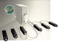
FIGURE 2. With the IEEE-1394 interface standard, it is possible to connect up to 64 devices (63 cameras and one interface board) to one bus interface. In practice, the available bandwidth sets the limit for the number of cameras that can be used. In this configuration, six cameras are attached to a PCI-based IEEE-1394 interface.
In the USB specification, isochronous data is an important issue. To accomplish the data rates needed between peripherals, specified bandwidths can be allocated as vision systems are configured. To reduce the effects of dropouts in the data stream, USB devices must provide buffering of these data; those devices requiring greater bandwidths support larger buffers. According to its specifications, the goal of USB-2 is to reduce this buffering-induced hardware delay to a few milliseconds.
At an IEEE-1394 forum held last May, Friedrich Dierks, manager of software development at Basler Vision Technologies (Exton, PA), discussed some important factors in specifying digital cameras for machine-vision systems. A key factor is the 1394 Trade Association (Santa Clara, CA) Digital Camera Specification (D-Cam Spec). "With an IEEE-1394 camera designed to the D-Cam Spec," says Dierks, "it is possible to use a standard set of messages to detect the camera on the IEEE-1394 network and to query the camera's capabilities."
These capabilities include programmable filters such as shuttering, balance, gain, and brightness. However, to support these capabilities, IEEE-1394-compliant cameras must be supplied with D-Cam-specific drivers. Theoretically, it is possible to connect up to 64 devices (63 cameras and one interface board) to one bus interface (see Fig. 2). In practice, the available bandwidth sets the limit for the number of cameras that can actually be used.
"As for USB-2, the standard is still in its infancy in machine vision, and I am not aware of any machine-vision support," says Dierks. Indeed, only at last May's USB Developers Conference did Microsoft Corp. (Redmond, WA) demonstrate Windows XP driver support for USB. At the conference, Carl Stork, general manager of Microsoft Windows hardware strategy, said that availability of USB-2 software support for developers shipping Windows XP-based products would be available later this year.
Dedicated designs
"For systems integrators who need high speed," says Dierks, "USB-2 and IEEE-1394 are not the first choice. On the other hand, these buses are the ones to consider where multiple cameras are needed and cost is a critical issue." Where very-high-speed area- and linescan cameras are required, isochronous image data are better transferred over a camera-to-frame-grabber link such as RS-422, RS-644, or Camera Link. The RS-644 interface is a low-voltage-differential-signal (LVDS) protocol that is backward-compatible with RS-422. However, unlike RS-422, RS-644 requires less power and allows longer cable lengths and higher clock rates.
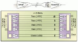
FIGURE 3. In operation, the Channel Link interface transmitter can convert 28 bits of data for transmission over four parallel lines. With one transmit clock, five pairs of wires can be used by Channel Link to transmit data that would require 56 wires in the LVDS interface method used in RS-644 (Figure courtesy of Pulnix).
Today, many frame-grabber and camera vendors support RS-644 differential parallel inputs up to the 40-MHz range. And, just as IEEE-1394b and USB-2 have or will emerge as replacements for their predecessors, vendors of high-speed area- and linescan cameras also will want to develop high-speed serial interfaces capable of interfacing cameras over longer distances.
To do so, a consortium of vendors led by Pulnix America Inc. (Sunnyvale, CA) have adopted a version of the Channel Link technology originally developed by National Semiconductor (Santa Clara, CA) to drive flat-panel displays. Called Camera Link, this standard is expected to replace RS-644 for high-performance digital cameras (see Vision Systems Design, Dec. 2000, p. 45). Unlike USB and IEEE-1394 protocols, however, the RS-422, RS-644, and Camera Link interfaces require separate drivers for each camera/frame-grabber combination.
As a camera-to-frame-grabber interface, the Camera Link specification defines data transmission, camera control, and asynchronous serial communications. With a maximum data rate of 1.9 Gbits/s over 10-m cable lengths, Camera Link LVDS technology needs fewer wires for data transmission. In operation, the Channel Link transmitter can convert 28 bits of data for transmission over four parallel lines. With one transmit clock, five pairs of wires can be used to transmit data that would otherwise require 56 wires in accordance with the standard LVDS methods used in RS-644 (see Fig. 3).
According to the 1394 Trade Association, more than 170 vendors are producing area-array cameras, interfaces, hubs, and peripherals in adherence to the IEEE-1394 standard. Unfortunately, at present, no similar association exists for the more than 50 vendors that offer area-array and linescan cameras and frame grabbers that meet the Camera Link specification. However, the Camera Link specification can be downloaded from the Automated Imaging Association (Ann Arbor, MI) Web site (www.machinevisiononline. org; search on keyword Camera Link).
In selecting a particular camera interface, systems developers must consider the price/performance trade-offs between bus and frame-grabber implementations. In practice, IEEE-1394 will more likely be used in applications that require standard video resolutions and rates, such as for microscopy, medical, and scientific applications. For its part, Camera Link will more likely be used for industrial applications that require high-resolution and high-rate area- and linescan cameras.
COMPANY INFORMATION
Automated Imaging Association
Ann Arbor, MI 48106
Web: www.machinevisiononline.com
Basler Vision Technologies
Exton, PA 19341
Web: www.baslerweb.com
Matrox Imaging
Dorval, QC, Canada H9P 2T4
Web: www.matrox.com/imaging
Microsoft Corp.
Redmond, WA 98052
Web: www.microsoft.com
National Semiconductor
Santa Clara, CA 95050
Web: www.national.com
Pulnix America Inc.
Sunnyvale, CA 94089
Web: www.pulnix.com
USB Implementers Forum
Portland, OR 97221
Web: www.usb.org
1394 Trade Association
Santa Clara, CA 95054
Web: www.1394ta.org


