SELECTING AN IMAGING DISPLAY MONITOR INVOLVES CRUCIAL CHOICES
SELECTING AN IMAGING DISPLAY MONITOR INVOLVES CRUCIAL CHOICES
Andrew Wilson, Edior at Large
According to Stanford Resources, a San Jose, CA, market-research firm, the worldwide market for cathode-ray-tube (CRT) computer-display monitors exceeded 84.2 million units shipped during 1997, at a sales value of nearly $21 billion. The company estimates that the aggregate worldwide market growth will remain consistent at a 5.1% rate from 1997 to 2003.
In this lucrative but highly competitive business, more than 60 monitor vendors are vying for market share. Unlike some electronics market segments, bigger is better in the monitor market. At last fall`s Comdex trade show, many monitor vendors unveiled higher-resolution, more-energy-efficient units with faster refresh rates and universal serial bus (USB) interface support.
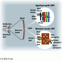
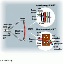
To choose a color monitor for image-processing applications, systems integrators must evaluate several important specifications, such as image resolution, dot or mask pitch, and refresh rate. Current color monitors use either aperture-grill or shadow-mask CRT technology to display detailed images (see Fig. 1).
In a shadow-mask CRT, phosphors are coated on the inside face of the cathode-ray tube in a red, green, and blue dot-pattern arrangement. During operation, red, green, and blue electron beams are directed through precision holes in the shadow mask to excite each respective color phosphor.
Similarly, in an aperture-grill CRT, phosphors are coated on the inside face of the CRT as long red, green, and blue vertical stripes. During operation, red, green, and blue electron beams are directed through a precision aperture grill to excite each respective color phosphor. By using a vertical array of wires to align the three electron beams, aperture-grill CRTs provide several advantages over their shadow-mask counterparts: they generally use a higher rate of electron-beam transmission, resulting in a higher-contrast screen image; monitor resolution does not depend upon the vertical spacing of pinholes, as in shadow mask tubes; and designs are less susceptible to heat warping.
To maintain proper vertical alignment in aperture-grill designs, horizontal damper wires are added. In Sony (Park Ridge, NJ) Trinitron monitors larger than 14 inches, for example, two horizontal damper wires are positioned approximately one-third the distance from the top to the bottom of the screen. According to Sony designers, each wire casts a faint shadow that is visible as a light-gray horizontal line on the image when the monitor displays a lightly colored background.
In aperture-grill monitors such as the Hi-Contrast CRT (Hitachi; Westwood, MA), resolution is determined by the stripe pitch or aperture-grill pitch--a measurement of the distance between the vertical wires or similarly colored phosphor columns.
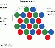
In shadow-mask designs, however, dot pitch, the distance between phosphor dots of the same color, is measured diagonally. Therefore, if a dot pitch is specified as 0.26 mm, for example, the horizontal spacing between phosphor dots of the same color is 0.22 mm, and the vertical spacing is 0.13 mm (see Fig. 2).
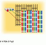
A variant of the shadow-mask design, invented by NEC Technologies (Itasca, IL), the ChromaClear CRT combines both shadow-mask and aperture-grill designs. Instead of using circular perforations in the shadow mask, the ChromaClear CRT uses elongated slot openings that the company claims results in improved brightness and contrast, as well as a reduced horizontal pitch (see Fig. 3).
Specifications
Understanding the types of CRTs available is just the first step in specifying a monitor. Size, resolution, and bandwidth are also key parameters. Confronted by diverse specifications, image-system designers must carefully examine monitor types. For example, many manufacturers provide two size numbers--the size of the CRT and the size of the diagonal viewable image. In the specifications of the P815 color monitor from ViewSonic (Walnut, CA), for example, the monitor is specified as having a 21-in. CRT and a 20-in.-diagonal viewable image size. This monitor presents a 406 ¥ 304-mm maximum display area.
Some vendors also list the maximum noninterlaced addressable resolution in conjunction with other specifications, such as aperture-grill pitch and display area. In the specifications of the DiamondPro 1010 color monitor from Mitsubishi (Cypress, CA), for example, addressable resolution is given as 1800 ¥ 1440 pixels. However, because the monitor`s display area is 400 ¥ 300 mm and its aperture-grill pitch is 0.26 mm, only 1538 ¥ 1153 pixels can be seen, despite the manufacturer`s higher-resolution claim.
Refresh-rate and line-scan rate monitors draw images one horizontal line at a time from the top left to the bottom right of the screen. As measurements of how many horizontal lines per second and how many screens are drawn per second, manufacturers specify horizontal and vertical scan rates. For any given resolution, the longer a monitor takes to write each line on the screen, the longer it takes to write the whole screen.
Although perceptible flicker is reduced at vertical refresh rates of 70 Hz and higher, the Video Electronics Standards Association (VESA) has developed an 85-MHz standard for flicker-free displays. The emergence of such standards is driving vendors to specify screen resolutions in conjunction with monitor bandwidth. For example, for the AcerView 98i 21-in. (19.9-in. displayable) color monitor, Acer America (San Jose, CA) specifies two maximum resolutions. At a refresh rate of 100 Hz, the screen resolution is specified as 1024 ¥ 768 pixels; at a lower 76-Hz rate, the screen resolution is 1280 ¥ 1024 pixels.
To achieve the desired resolutions at specified refresh rates, the bandwidth of the monitor must also be carefully considered. In the AcerView 98i monitor, the 135-MHz specified video bandwidth should accommodate the screen resolutions at the refresh rates specified, including the time taken for horizontal and vertical sync pulses. Here again, however, specifications can be misleading. Increased screen resolution comes at the price of a lower refresh rate, and, in choosing a high-resolution monitor, system designers and integrators should select those with sufficient bandwidth.
Convergence and focus
Improvements in monitor electronics and CRT designs are also reducing the effects of two important aspects of high-resolution monitors: convergence and focus. Convergence refers to how well the three primary colors form a white area on-screen; focus indicates how well the images transition from white to dark areas. The monitor electronics and CRT designs are generally not specified on data sheets from manufacturers. To further improve both designs, however, monitor manufacturers are using more sophisticated deflection yokes and electronics.
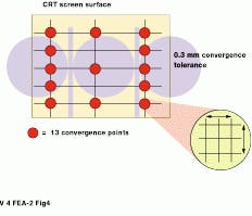
In the manufacture of its GS Series of monitors, Sony applies a Digital Dynamic convergence process to adjust and meet convergence tolerance specifications. Previously, trained technicians added a small metallic strip between the defection yoke and the CRT neck to adjust the convergence in two zones of the display (see Fig. 4). Now, a specially equipped camera takes measurements at 13 points on the surface of the CRT. These measurements are fed to a waveform generator that sets convergence processors attached to the deflection yoke. After monitor calibration, the processors automatically make the proper convergence adjustments.
Similarly, proper focusing depends on the qualities of the deflection yoke and the electron-beam gun. However, in shadow-mask designs, proper focusing can result in other problems such as raster moiré effects. Because of the construction of the raster mask, a well-focused CRT means only that the proper phosphor dots are illuminated. But, unfortunately, areas where the light has been blocked become more apparent, showing up as dark circular patterns that result in a moiré effect. To compensate for this and other distortion effects, some manufacturers are incorporating digital-signal-processing (DSP) techniques into their monitors. In the design of its F67 and T68 monitors, for example, Eizo (Cypress, CA) has developed a digital-signal processor that generates the waveforms needed to correct for screen distortion and to reduce moiré effects.
Plug and play
To make the connection of peripherals easier, including computer monitors, computer and electronics companies such as Compaq, DEC, Intel, Microsoft, NEC, and Northern Telecom have formed a consortium to promote the USB as a standard. Personal computers equip ped with the USB allow computer peripherals to be automatically configured as soon as they are physically attached, as well as allowing plug-and play operation.
Drawing its intelligence from the PC, the bus detects when peripheral devices are both added and removed. It automatically determines what host resource, including driver software and bus bandwidth, each peripheral needs and makes these resources available without user intervention.
In the design of its T68 19-in. tension mask monitor, Eizo incorporates an integrated USB hub for access to other USB peripherals such as scanners, mice, and keyboards. This hub contains one upstream port for the PC and four downstream ports for peripherals.
By connecting computers over a USB interface, detailed monitor adjustments such as size, position, and convergence can be made using the computer and vendor-supplied software. This bus standard makes it easier to adjust monitor parameters and to reduce monitor set-up times.
Radiation hazards
With the emergence of strict Swedish environmental standards, monitor vendors must deal with another design problem--acceptable emission values for magnetic and electric radiation. Established in 1987 as a voluntary guideline, the so-called MPR standard developed by the Swedish Board of Technical Accreditation set the first standard on acceptable emissions for monitors. In 1990, the standard was updated to MPR II and incorporated even tighter monitor-radiation requirements than its predecessor.
In 1989, the Swedish Confederation of Professional Employees announced its own monitor-radiation standard, called TCO. In 1992, this standard was upgraded to include power-saving recommendations and compliance with European fire and electrical safety requirements. These requirements were even more restrictive than the MPR II standard. In 1995, the TCO standard was further expanded by incorporating recycling requirements and chemical limitations.
These Swedish monitor specifications are finding their way onto the data sheets of monitor manufacturers. For example, MPR-II adherence is listed on the CC-617 17-in. color monitor from Sceptre (City of Industry, CA). ViewSonic specifies TCO-95 compliance on its P815 21-in. monitor.
Systems integration
For low-cost image-processing applications, a PC-compatible monitor is generally satisfactory. For these monitor types, referring to monitor manufacturers` Internet sites can provide a useful starting point. Most sites enumerate the key monitor specifications.
In medical imaging applications, such as where ultrahigh-resolution gray-scale levels are required, the choice of monitor manufacturers is limited. Typical companies include Dotronix (New Brighton, MN) and Clinton Electronics (Rockford, IL). When specifying medical imaging monitors, system integrators should look for both USB and MPR standards.
FIGURE 1. In fabricating a shadow-mask cathode-ray-tube (CRT), phosphors are coated on the inside face of the tube in a red, green, and blue dot-pattern arrangement. In building an aperture-grill CRT, phosphors are coated on the inside face of the CRT in long vertical red, green, and blue stripes.
FIGURE 2. In shadow-mask CRT designs, the dot pitch of same colored dots is measured diagonally. Typically, when the dot pitch is specified as 0.26 mm, the horizontal spacing between phosphor dots of the same color is 0.22 mm, and the vertical spacing is 0.13 mm.
FIGURE 3. In a variation of the shadow-mask CRT design, invented by NEC USA, the ChromaClear CRT combines both shadow-mask and aperture-grill methods. Instead of using circular perforations in the shadow mask, ChromaClear uses elongated slot openings that result in improved brightness and contrast and a reduced horizontal pitch.
FIGURE 4. Sony uses Digital Dynamic convergence to adjust convergence tolerance specifications in two zones of the display. During operation, a specially equipped camera takes convergence measurements at 13 points on the surface of the CRT. The measurement data are fed to a waveform generator that provides adjustment signals to convergence processors attached to the CRT deflection yoke.
