SELECTING THE RIGHT lighting method FOR MACHINE-VISION APPLICATIONS
SELECTING THE RIGHT lighting method FOR MACHINE-VISION APPLICATIONS
By Andrew Wilson, Editor at Large, and John Haystead, Contributing Editor
Since Thomas Edison invented the first incandescent light source in 1879, lighting-source developers have been designing a range of alternate illumination sources to increase lamp efficiency, brightness, and lifetime at lower cost. For machine-vision-system designers, illumination choices now include incandescent, fluorescent, compact-fluorescent, plasma-type, high-intensity discharge (HID), light-emitting-diode (LED), fiberoptic, and structured light sources.
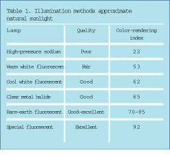
While each illumination source has merits in terms of power, efficiency, quality, life, and stability (see table on p. 64), still other factors must be considered when choosing an imaging lighting system, especially if the object is to be inspected by a color machine-vision system (see "Searching for a sunlight source," p. 59).
Lighting sources
Incandescent lamps are the most common types of light sources. In operation, light is produced by passing an electric current through a wire filament. Their advantages include low cost, tight optical control, and broad-spectrum characteristics. However, as incandescent lamps operate at relatively high current levels, they generate considerable heat. Worse, if such lamps are operated on direct current (dc), the average lamp life can be shortened by as much as 50% because dc accelerates the grain growth of the tungsten filament, leading to the development of hot spots.
Moreover, as incandescent lamps age, they become increasingly vunerable to failures from shock and vibration; in addition, the filaments are embrittled by grain growth. If such lamps are used in industrial areas, maintaining the longest life can be accomplished by using low-voltage lamps or operating them at less than their rated voltage.
Halogen lamps also produce light by passing current through a thin wire filament; but here, the filaments operate at higher temperatures. Because of high heat, the color rendering index (CRI) of halogen lamps is higher, producing whiter light than standard incandescent lamps. Newer halogen infrared (IR) lamps come with a coating on the inside of the bulb that traps the IR heat energy without sacrificing light output. This trapped heat increases lamp efficiency.
"The cost of parts, installation, and power supplies associated with halogen lamps is relatively low," says Mike Muehlemann, president of Illumination Technologies (East Syracuse, NY). "But the light produced by them is blue-deficient, producing a reduced number of photons from the red to blue end of the spectrum," he adds. The lifetime of these systems is also relatively short compared to other technologies, which increases maintenance costs and downtime.
With an average lamp life of 5000 hours, the Xtra-Life family of halogen lamps from Litronics International (Alsip, IL) is available in 55-, 68-, and 78-W types in a variety of sizes. According to the company, the lamps achieve more than twice the lifetime of other halogen lamps through a combination of gasses and a specially developed tungsten filament.
Improved ballasts
Since their introduction at the New York World`s Fair in 1939, fluorescent lamps have proven four times more efficient and 10 to 20 times longer lasting than their incandescent counterparts. Lamp manufacturers have continually improved their designs and are now providing lamps similar to those of warmer incandescent lighting while reducing flickering effects and noise with improved ballasts. Such ballasts furnish a high initial voltage to start the gas discharge, then rapidly limit the lamp current to sustain the discharge. Although optimally designed to operate a unique lamp type, some ballasts can operate more than one type of lamp. In such cases, though, optimum lamp-starting characteristics, light output, and operating life might not be achieved.
Because of their smaller diameters and folded configurations, the latest compact fluorescent lamps offer high light output in much smaller sizes than conventional linear fluorescent lamps. Available in a variety of plug-in and built-in ballast designs, these compact lamps deliver the same light output as incandescent lamps at nearly one-fourth the cost.
Other types of gas-discharge lamps include high-pressure sodium (HPS) and metal-halide lamps. Like fluorescent lamps, both HPS and metal-halide lamps require ballasts for proper operation. "Because a gas is ignited in these lamps," explains Muehlemann, "these lamps have a high color temperature output." High-pressure sodium lamps can last up to 40,000 hours and, when compared to tungsten halogen lamps, can generate seven to eight times more visible photons, he contends.
Stabilized light
Conventional metal-halide lamps incorporate a third electrode, or probe, in their arc tube as a starting aid; they are, therefore, sometimes referred to as probe-start lamps. The starting voltage induces a small glow discharge and creates, or strikes, the inside surface of the arc tube. As the arc voltage rises, the vaporization of the mercury and metallic compounds increases, and the light becomes brighter. A small bi-metal switch then disconnects the starter electrode after the arc has stabilized.
Because it takes some time to attain the intense heat and pressure required inside a metal-halide lamp`s arc tube, the brightness and color might not stabilize in probe-start lamps for as long as 20 minutes. Last month, Philips Lighting (Somerset, NJ) introduced five 175- to 1000-W pulse-start metal-halide lamps. Because these lamps use high-voltage pulses, run-up time is faster and restrike times are less than five minutes, compared to as long as 20 minutes for probe-start lamps.
Light distribution
While many arc lamps provide good luminous intensity, the distribution of light over the arc is nonuniform. In imaging applications, such as microscopy, where uniform illumination is mandatory, this shortcoming limits the resolution obtainable by the microscope.
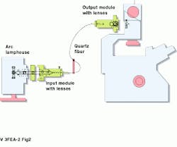
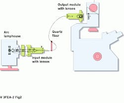
To overcome these limitations in microscopy, Technical Video (Woods Hole, MA) has developed a fiberoptic light scrambler. In operation, these devices use lenses and a single step-indexed silica fiber to transform a nonuniform light source into a uniform disk of light that is transmitted into the microscope (see Fig. 1 on p. 57). This method dramatically improves the resolution of microscope images.
In many machine-vision systems, LED lamps are fast becoming the imaging designers` choice. These lamps supply solid-state, long-lasting, highly efficient and maintenance-free illumination. Although such light sources have, up until now, been monochromatic, manufacturers such as Advanced Illumination (Stockbride, VT) have developed lamps that use red, green, and blue LEDs to produce a white-light source (see Vision Systems Design, Feb. 1998, p. 15).
"LED lamps are easy to focus compared with lens-based systems and are finding increased applications in gauging and measurement applications," claims Muehlemann. Although they have limited output power, LEDs can have lifetimes of 10,000 hours or greater.
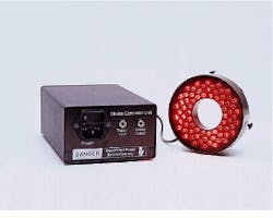
Typical of such lamps are the LED UltraLight Series from August Technology (Edina, MN). With a rated lifetime of 100,000 hours (10 years of continuous use), the LED lamps use less than 7 W and are available in a range of wavelengths (see Fig. 2 on p. 57). Using a lens-mount-adapter ring, the UltraLight Series is easily attached to most CCD cameras.
Structured lighting
Illuminating an object from a known angle with a specific light pattern and observing the lateral position of the image have proven useful in determining depth information. Such structured lighting techniques have been widely used for defect detection in the automotive, electronics, and semiconductor industries. In operation, they generate a line of laser light, which is viewed obliquely, and the distortions in the line are translated into height variations. This information is used to structure the three-dimensional (3-D) shape of the object.
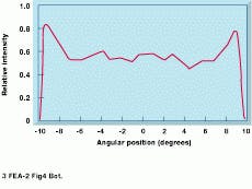
However, using the wrong type of laser for illumination can cause problems. Many laser line generators use cylindrical optics to expand the beam in one direction and generate a Gaussian line that is bright in the center. Because the light intensity of Gaussian lines fades as the laser moves from the center, the illumination often can fall to a level below that of the detector, thereby becoming invisible to the system. And, because the light intensity is not uniform, charge-coupled-device (CCD) calibration is difficult. To overcome this, manufacturers such as Lasiris (St Laurent, Quebec, Canada) have produced patented optical designs that produce non-Gaussian, evenly illuminated lines of laser light that permit a simple CCD calibration (see Fig. 4).
In the past, choosing a lighting system for a machine-vision application was often the last design decision. Now, however, with the large number of lighting choices available, the choice of lighting can save time and money and reduce the development time of the imaging system (see "Illumination keeps vision on the ball," p. 65). Indeed, with the proper choice of illumination developed at the onset of a machine-vision-system project, designers may find that hardware and software costs can be reduced.
FIGURE 1. By incorporating a fiberoptic light scambler, arc lamps can eliminate the effects of nonuniformity. Using standard arc illumination reduces the resolution of the image. After the light is scrambled, the resolution of the image is increased.
FIGURE 2. Light-emitting diode lamps are targeted toward machine-vision and robotic inspection systems. According to the company, the lamps feature a rated file of 100,000 hours of continuous use.
FIGURE 4. In structured lighting systems, a Gaussian laser source makes CCD calibration difficult (left). By using a patented lens system, the Gaussian response can be flattened, making calibration easier (right).
Searching for a sunlight source
Machine-vision systems are often required to examine parts or labels that carry color printing. For these inspections, the color rendering of such light sources is extremely important. Because natural light has an even balance of blue, green, yellow, orange, and red in the visible, lamps that emulate natural lighting must, as closely as possible, follow this spectrum. If the spectrum of such lamps is closely balanced to the spectrum of natural light, the lamps are called full-spectrum lamps.
To characterize such lamps, two indexes are often used--the color rendering index (CRI) and the correlated color temperature (CCT) index. While the CRI describes the light source`s ability to accurately render the color of perceived objects, the CCT refers to the warm or cool ambiance created by the light source. CRI values extend from 100 (the reference standard of incandescent sunlight) downward (see Table 1). As listed, the higher the CRI value, the closer the light source renders the object`s color to its color appearance under the reference source (see Fig. A).
Unfortunately, a high CRI does not necessarily guarantee accurate color rendering because the color of an object depends on the portion of the spectrum emitted by the light source, the color reflected, and the specifications of the imaging system. Expressed in Kelvins (K), the CCT value attributed to a light source indicates its ambiance. While lower numbers (2100 K) indicate warmer reddish and yellow sources, higher numbers (4500 K to 7500 K) reflect cool to blue ambiance (see Table 2). Despite the long-time use of these indices, many imaging-system designers remain skeptical of their usefulness.
"The most common claim to simulating daylight is done in the commercial fluorescent-lamp industry," says Kevin McGuire of Tailored Lighting (Rochester, NY), a manufacturer of natural daylight lamps. "Poorly defined phrases such as "full spectrum" are misunderstood, and misleading terms such as CRI are marketing tools to convince customers that fluorescent lamps accurately simulate daylight," he insists.
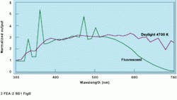
Indeed, to compare the spectrum of natural light to lamps, spectral power distribution curves are required. These curves show the amount of power generated in each spectral band (ultraviolet and visible regions of the spectrum). If the match of the lamp is 90% or greater to that of natural light (including near and middle ultraviolet), then the lamp is a full-spectrum device.
"A spectral comparison of a phosphor fluorescent lamp light and natural daylight at the same correlated color temperature shows that the spectral spikes typically emitted by fluorescent sources are not found in natural daylight," says McGuire (see Fig. B).
Standard incandescent lamps (including tungsten-halogen lamps) cannot provide the spectrum found in daylight because the lamp filaments would vaporize if heated to the point where they would provide the correct color to simulate daylight. Typical tungsten-halogen lamps have a deficit of blue light and a surplus of yellow and red when compared to 5000 K daylight. High-intensity discharge lamps are more recent types of lamps claimed by several manufactures to simulate daylight. However, a comparison between these sources and daylight at the same CCT index reveals extreme spectral discontinuities.
A. W.
FIGURE A. Differences in illumination can radically alter the appearance of a color object. Here, the image is illuminated with (from top to bottom) a GE cool white lamp with a color rendering index (CRI) of 62, a GE SP35 lamp with a CRI of 73, and a GE SPX 35 lamp with a CRI of 82.
FIGURE B. When the spectral power distribution of daylight and "daylight fluorescent" lamps are compared, the spectral spikes emitted by fluorescent lamps are clearly revealed.
Illumination keeps vision on the ball
For the Titleist Golf Ball Operations (Dartmouth, MA) custom printing line, the goal is not to get the golf ball into the cup, but to make sure the ball is facing right side up, every time, for printing purposes. To ensure that each golf ball is properly positioned for the printing of private-label logos, the company uses a custom-built robotic orientation system from Intelligent Automation Systems (Cambridge, MA). While manual operators can place just fewer than 400 dozen balls per shift, an automated orientation system can handle 1000 dozen balls and place as many as 1600 dozen during the same time period. Controlled by machine-vision optics and processing, the imaging system depends heavily on the performance of its lighting system for the task.
Golf balls present several illumination challenges for a machine-vision system. Prior to the printing of custom logos, each golf ball is preprinted with the Titleist logo, stripes, and numbers. The machine-vision system must quickly and accurately identify the position of these printed features to direct the next orienter process. But in addition to their curved, dimpled surfaces, the golf balls are coated with a glossy lacquer finish, requiring tight control of light intensity and position to eliminate glare.
During operation, the machine-vision-system camera looks both at a direct view and a mirror-reflected side view of each golf ball. An adjustable Illumination Technologies (East Syracuse, NY) eight-point, fiberoptic ringlight mounted to the face of the camera precisely positions the light on the golf ball from above. While this setup removes the majority of glare, cross-polarizing filters are used to reduce any remaining hot spots.
The mirrored view posed special challenges for the setup of the polarizing filters. According to Peter Mansfield, former principal researcher at Intelligent Automation Systems (Cambridge, MA) and now an independent machine-vision lighting consultant, this method relates to the principle that light incident on a surface at a shallow angle will be reflected with a polarized component. As a result, additional glare problems are imposed by both the light reflected from the mirror and the light reflected from the mirror off the golf ball (see Fig. 1s).
To deal with the glare problem, the filter on the light source was removed, and the camera filter was rotated to block as much glare as possible from the ball. This approach attenuated the polarization caused by the reflection from the golf ball itself. Next, the light-source filter was replaced and rotated to block the remaining glare from the golf ball.
According to Paul Furze, Titliest senior automation engineer (New Bedford, MA), the polarizing filters were a big factor in improving contrast. "Before the filters were used, there was a limited range at which the light intensity could be set. If it was set too bright, the printing would wash out and cause orientation problems. Now the light-intensity range settings are much less stringent."
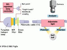
While the Titliest name is always printed in black, different golf-ball types have different colored numbers and stripes. To assist the monochrome camera system in locating this color printing, Illumination Technologies used a spectrophotometer to generate the spectral reflectance curves of the different paints used. From these data, specific white-light filtration schemes were incorporated to enhance the contrast between colors. Initially, color filters were laid directly on top of one of the polarizing filters. However, these filters were later moved from the camera and placed immediately in front of the lamp (see Fig. 2s).
According to Furze, Titleist is now working on a next-generation orientation system that will orient unprinted golf balls through examination of their dimples.
J. H.
FIGURE 1s. A high-contrast image is acquired with a monochrome system using spectrally selective contrast enhancement. The graph shows the spectral reflectivity of a custom purple logo and the spectral transmission of the green filter used to provide a maximum contrast ratio. The purple logo shows minimal reflection of wavelengths between 475 and 575 nm. Because the golf ball is white, light provided at these wavelengths produces high gray-scale values for the ball and low gray-scale values for the purple logo.
FIGURE 2s. By adjusting the angle of the eight fiberoptic outputs of the golf-ball-orientation illumination system, the standard adjustable annular ringlight provides uniform brightness on the spherical object. The concave geometry of the dimples on the golf ball surface, combined with the specular surface, present a difficult glare problem that is addressed by a combination of linear polarizers. A 3900 K light feedback source, with a green interference bandpass filter, is used to power the ringlight. The light-feedback system maintains a short-term, light-output stability within less than 0.1% deviation and a long-term drift below 1%. Intensity values can be pre-stored and loaded via a serial communications link (RS-232 or 485).
