Novel CCD improves low-light-level astronomy images
Novel CCD improves low-light-level astronomy images
Lawrence J. Curran
contributing editor, and others*
Research astronomers at the University of Hawaii (UH; Honolulu, HI) and the Massachusetts Institute of Technology (MIT; Cambridge, MA) have designed and fabricated a new type of charge-coupled device (CCD) that uses a novel technique to remove image motion caused by atmospheric turbulence. Called an orthogonal-transfer charge-coupled device (OTCCD), it permits parallel clocking horizontally as well as vertically by moving the electrons within the CCD to follow the optical image falling on the device.
The OTCCD removes the image motion caused by atmospheric turbulence at rates up to 100 Hz and promises to be a faster, cheaper, and more elegant way to carry out image-motion correction than by using fast tip/tilt mirrors. The latter is a standard method that removes motion by including a mirror in the optical train, which can be tilted in two directions, thereby steering the image to compensate for motion.
The OTCCD developers also report that the large number of transfers needed to track image motion does not significantly degrade the image, either because of charge-transfer inefficiency or because of charge traps, which can cause dark spots in an image.
Data gathered over four nights at the Michigan-Dartmouth-MIT (MDM) 2.4-m telescope at Kitt Peak National Observatory (Tucson, AZ) also indicate that the atmosphere is "surprisingly benign in terms of both the speed and the coherence angle of image motion. Image-motion compensation has improved image sharpness by about 0.5 arc sec in quadrature, with no degradation over a field of at least 3 arc min," concludes John Tonry, professor of astronomy at the University of Hawaii. He adds that the degree of improvement is similar to results using tip/tilt mirrors.
The OTCCD is housed in a cryostat that cools it and serves as the cornerstone of a system that also includes a Sun Microsystems (Palo Alto, CA) Sparcstation 2 workstation, a Motorola (Phoenix, AZ) digital-signal processor (DSP), a split serial register with amplifiers at each end, and considerable custom software, most of which was written by Tonry. The software includes code for both the DSP and the Sun SparcStation. The DSP commands an analog board from San Diego State University (CA) incorporating "a lot of DACs and buffering amplifiers," Tonry says.
In operation, the SparcStation downloads a program to the DSP, which the DSP runs. Part of this program sends out digital words addressed to a particular digital-to-analog converter (DAC). In turn, the DAC converts the words into a voltage, buffers the voltage, and applies it to the OTCCD chip. "This is how the charge is clocked back and forth within the CCD," Tonry says, "and because it is all digital, it is easy to change voltages and tweak up performance."
The DSP also controls a signal chain, which comprises a preamplifier (connected to the CCD output amplifier), a dual-slope integrator (for correlated double sampling), and a 16-bit ADC. In addition to a commercial S-bus parallel-interface device, the other key system element is a custom fiberoptic interface, "which communicates to the DSP box hanging out on the telescope and converts the information to normal parallel information," Tonry says.
Image distortion occurs because light from a distant object passing through the atmosphere suffers phase distortions, causing the image of the object to dance and blur. These distortions are caused by turbulent density fluctuations in the air, which translate to fluctuations in the index of refraction. The fluctuations are considered stationary in time, but when blown across a telescope aperture by the wind, they cause the wavefront of a point source to become a rapidly varying fractal landscape. Tonry says the distortion of an optical wavefront "is a complicated mess" that can be likened to the turbulence of an ocean surface that includes large waves, small wavelets, and even smaller ripples.
Turbulence is a random phenomenon, but it obeys certain scaling relations. The Kolmogorov theory of turbulence describes how turbulence in the atmosphere leads to temperature, density, and index-of-refraction variations that distort images. As in the ocean-surface analogy, Tonry says that "in particular, there is a so-called `energy cascade,` in which the medium gets stirred up on large scales, causing turbulence on smaller and smaller scales until the energy disappears via viscosity into heat."
Compensating for turbulence becomes an obstacle to obtaining image quality. A common and robust way to characterize image quality is applying the full width at half maximum (FWHM) of a point source. Typical astronomical "seeing" might have a FWHM of 1 arc sec at 500 nm, which corresponds to the diffraction limit of a telescope with an aperture of about 10 cm. When a telescope aperture is larger than this value, the light from all these sized subapertures interferes at the focus to produce a rapidly changing speckle pattern.
Correcting the wavefront to recover the diffraction-limited performance of an aperture is known as adaptive optics. It requires phase corrections for each 10-cm-sized subaperture of the telescope on time scales that are roughly the time (ms) it takes the wind to blow a distance of 10 cm.
Instruments have been built to compensate for image motion; most of them work by incorporating a mirror into the light path. The mirror is rapidly tilted to steer the light. The challenge of these devices is to make the moving element stiff and light enough to push resonances to high enough frequencies so that it maintains a stable control loop at 20 to 50 Hz. "This is a significant engineering achievement but it is usually expensive, particularly in the most ambitious projects, where the telescope secondary is articulated," Tonry notes.
The gains from using these devices are significant. Image motion from the atmosphere can be stopped, and any telescope shaking can be removed. Nevertheless, these devices are often difficult to use, offer small gains, and cause enough degradation in images (loss of light, nonuniform point-spread function (PSF) and setup overhead) that most images taken today do not benefit from image-motion compensation, other than using a standard autoguider sampling at rates less than 0.5 to1 Hz.
A telescope uses drives that run all the time to track star motion. "You can modulate this tracking rate a bit to compensate for image motion (or usually telescope motions)," Tonry says. "This is a standard autoguider, but it can`t react very fast because it is pushing a 100-ton telescope with a 1-hp motor."
Another approach
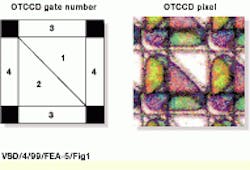
The UH-MIT researchers achieve image-motion compensation differently; they move the electrons within the CCD to track the optical image captured by the device. The OTCCD, which was designed and built at MIT Lincoln Laboratory (Lexington, MA), substitutes a fourth gate for the usual channel stop, permitting side-to-side parallel clocking of charge as well as up-and-down clocking.
The first device implemented just 64 x 64 pixels, but it demonstrated that the concept worked and that it was possible to shift a developing image within a CCD to any position. The next device design used to collect engineering and scientific results at the MDM telescope used 512 x 512 pixels and an equal-size frame-store region. Tonry says the advantages of the OTCCD are that it can shift charge much faster than an optical image is likely to move (within approximately 100 μs). Moreover, it suffers from none of the problems incurred with moving optics, and it is an inexpensive option to build into a CCD (see Fig. 1).
In a normal CCD, the fourth phase would be a channel stop implant, whereas in the OTCCD, the channel stops are small implants at the corner of each pixel. "If this fourth phase is set low, however, it acts as a conventional channel stop, and we can clock the charge in the device down with the three-phase sequence 1--2--3--1 or up with the sequence 1--3--2--1," Tonry explains.
But the researchers have also altered the geometry of the two central phases, 1 and 2, into triangles that are rotation symmetrical; the third phase is symmetrical with phase 4, so that they can also clock charge left and right. "This is achieved by setting phase 3 low and using the sequences 1--4--2--1 for right movement or 1--2--4--1 for left movement. For normal integration, we set both phase 3 and phase 4 negative and collect under phases 1 and 2," adds Tonry.
Starting small
The first 64 x 64-pixel test device that worked as expected was too small for effective tests of charge-transfer inefficiency or rate of incidence of pockets and traps. However, space was available in a mask set for another CCD development program, "and we seized the opportunity to build a larger OTCCD," Tonry reports.
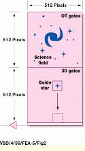
To make a device that could track image motion without any external inputs, the researchers built a chip with a 512 x 512-pixel array of orthogonal-transfer (OT) gates and a 512 x 512-pixel array of conventional three-phase gates. "The lower portion of the chip could be used as a frame-store area, but we chose to leave it uncovered so that it could be used to track a guide star. Both arrays dump into a split serial register with amplifiers at each end," Tonry notes.
"We wanted this CCD to be simple in use, so we kept the number of clocks to 12 so that the OTCCD could be run with a single San Diego State University analog board (four OT gates, three three-phase gates, three serial gates, a summing well, and reset). The pixels are 15 μm square, which translates to 0.17 arc sec at the MDM 2.4-m telescope, and the chip has a view equal to 1.5 x 3 arc min," Tonry explains.
Because of financial constraints and because they didn`t want to introduce any processing that might jeopardize the standard three-phase devices on the same wafer, the researchers chose aluminum to fabricate the topmost gate (No. 1). Subsequent experiments indicated that the aluminum increased the incidence of pockets, which caused dark holes in the images. These experiments also showed that substituting an alloy of titanium-tungsten-aluminum for the aluminum dramatically reduced the incidence of pockets under the OT gates.
Telescope operation
In operation, the telescope is first positioned to place the field of interest on the OT region of the chip (see Fig. 2). Next, a suitably bright guide star is sought, usually by rotating the instrument. "For the observations at Kitt Peak, we used a front-side-illuminated device (in which aluminum covers about 60% of the chip), so the quantum efficiency was low," according to Tonry. "We could track at 10 Hz on stars with a magnitude of 15.5. The probability of finding a star within the 1.5-arc min field at this brightness is about 0.6 at the north galactic pole; so, for some fields we had to track more slowly than 10 Hz," he adds.
The next-generation back-side illuminated OTCCD devices are expected to improve this tracking by about 1.5 magnitudes, "and we can improve the signal-to-noise ratio of our guide star detection by a factor of about 2 (another 0.7 magnitude). This will raise the probability of finding a guide star for 10 Hz within 1.5 arc min to greater than 0.9," Tonry says.
The UH-MIT team uses "shutterless video" to read out guide star information while the OTCCD is integrating on the science field. This method is applicable to any CCD and is the usual way at MDM to focus the telescope.
As the observation proceeds, each guide star image is piped to a CRT display, which shows the current centroid or image center, a leaky average of the guide star images, and a strip chart of the image FWHM. Tonry comments that one of the attractive features about OT tracking is that if the telescope focus drifts, the observer can refocus in real time without worrying about causing the image to move.
When the exposure has finished, the entire CCD reads out the data, and the science image in the OT region is saved to disk. "We also save a complete record of time, guide star position, and image shifts for each guide sample. This is necessary to create a flat field because the science image has been dithered over many OTCCD pixels," says Tonry.
The team uses the OT guide star information purely for OT tracking, "and we depend on the usual telescope autoguider to guide the telescope. This is a matter of expediency, and we can probably improve performance a bit, and make the observer`s job simpler, by using a suitably filtered version of the OT guide star motion to move the telescope," Tonry observes.
The biggest concern about the viability of image-motion compensation within an OTCCD was that traps or pockets might cause serious "pocket-pumping." For example, a bulk trap of only one electron depth might store an electron during each shift and release it later, potentially digging a 5000-electron hole in the image and building up a 5000-electron spike. "Because typical exposures have sky levels of only a few hundred to a thousand electrons, this will seriously degrade the image. But our experience showed that not to be a problem," Tonry reports.
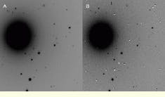
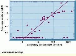
The OTCCD performed well when it was applied to the MDM 2.4-m telescope. "What was surprising was the fact that the pockets were much less pronounced than we had feared. Figure 3 shows an image of the galaxy NGC 6703 at a contrast level that shows 1% deviations from the sky level. About 20 pockets are apparent, but the rest are nearly invisible. Figure 4 shows the size of the pocket (in electrons per transfer) measured in this image versus the pocket size measured in the laboratory.
The proof
"Although the visibility was not always this good, we almost always achieved this level of improvement [described as removal of 0.5 arc sec in quadrature or reduction in FWHM by 20%] over normal guiding by use of OT tracking," Tonry reports (see Fig. 5). "Perhaps even more remarkable, we never saw any degradation of the PSF across the OTCCD, which implies that the motion of the guide star and science field must be highly correlated across at least 2.5 arc min," he adds (see Fig. 6).
The charge-transfer efficiency of the OTCCD is good enough (better than 0.999993) that a normal exposure consisting of thousands of shifts will not significantly degrade the PSF. The use of OT tracking sharpens images to approximately 80% of their normal size, or alternatively, OT tracking removes about 0.5 arc sec in quadrature from the image FWHM. The FWHM of image motion is roughly 60% of the FWHM of the PSF, which is in good agreement with the Kolmogorov theory of turbulence.
Tonry says, "Our current effort is building an OTCCD device of 2048 x 4096 pixels with four regions that can be clocked independently. This approach will make it more convenient and simpler to perform the entire job of sensing and compensating for star motion with one standard set of CCD electronics" (see Fig. 7).
FIGURE 1. Schematic diagram shows how the four gates of an orthogonal-transfer charge-coupled device (OTCCD) are organized (left). The photomicrograph depicts an OTCCD pixel (right). Gate 1 is made of aluminum and appears bright.
FIGURE 2. An orthogonal transfer charge-coupled device (OTCCD) is used to track image motion by placing the science field on the portion of the CCD with OT gates (top) and a guide star on the frame-store portion of the CCD (bottom). A subarray containing the star image is rapidly read out and used to correct the position of the charge within the OT array to follow the motion of the field.
FIGURE 3. For these two images of the galaxy NGC 6703, the left image (A) was taken with a Loral CCD using normal guiding and had an equivalent exposure of 5000 s. The right image (B) shows the results of 4650 shifts during a 500-s exposure. The PSF FWHM is 0.82 arc sec on the left and 0.58 arc sec on the right. The stretch is adjusted to make the pockets stand out.
FIGURE 4. The size of pockets in images derived during actual observing is plotted against the size of the same pockets derived from pocket pumping experiments in the laboratory. The line illustrates a reduction factor of 30 in size.
FIGURE 5. Two 150-s images of globular cluster M71 taken in immediate succession illustrate the improvements achieved with OT tracking of image motion. The left image (A) panel shows an image of the globular cluster M71 with ordinary guiding when visibility was very good (0.73 arc sec). The right image (B) had 1113 OT shifts applied to improve imaging and OT tracking was carried out at 7 Hz (0.50 arc sec).
FIGURE 6. Two small portions of Fig. 5 are shown in greater detail. The left images (A and C) were obtained with ordinary tracking. The right images (B and D) were obtained with OT shifting. The upper images (A and B) are about 2 arc min from the guide star. The lower images (C and D) are about 0.5 arc min from the guide star.
FIGURE 7. Orthogonal-transfer charge-coupled device (OTCCD) is deployed at the Kitt Peak National Observatory. The device is kept cool in a cryostat mounted in close proximity to the telescope`s focal plane. The OTCCD drive electronics include a DSP that accepts programs downloaded from the Sun SparcStation over a fiberoptic link. The DSP sends digital words to digital-to-analog converters on an analog board, which are converted to voltages and applied to the OTCCD to clock the charge horizontally and vertically to follow the optical image falling on the OTCCD.
*Portions of this article were excerpted from The Orthogonal Transfer CCD, presented at the 1997 meeting of the Astronomical Society of the Pacific by John L. Tonry, Institute of Astronomy, University of Hawaii, Honolulu, HI, and Department of Physics, Massachusetts Institute of Technology, Cambridge, MA; Barry E. Burke, Lincoln Laboratory, Massachusetts Institute of Technology, Lexington, MA; and Paul L. Schechter, Department of Physics, Massachusetts Institute of Technology, Cambridge, MA. The research was supported by NSF grant AST-9314665. Supplemental details were reported by Lawrence J. Curran, contributing editor.
Company Information
CCD Laboratory
Astronomy Department
San Diego State University
San Diego, CA 92182-1221
(619) 594-6182
Fax: (619) 594-1413
Web: mintaka.sdsu.edu
MIT Lincoln Laboratory
Lexington, MA 02173
(781) 981-0680
Fax: (781) 981-9597
E-mail: [email protected]
Motorola Semiconductor Products Sector
Phoenix, AZ 85008
(602) 244-3742
Web: www.motorola.com/sps/
Sun Microsystems Inc.
Palo Alto, CA 94303
(650) 960-1300
Fax: (650) 856-2114
Web: www.sun.com
University of Hawaii
Institute for Astronomy
Honolulu, HI 96822
(808) 956-8701
Fax: (808) 956-9590
Web: www.ifa.hawaii.edu
