Navy divers and sonar imaging detect covert mines
Navy divers and sonar imaging detect covert mines
By John Haystead, Contributing Editor
The Applied Physics Laboratory (APL) of the University of Washington (Seattle, WA) has developed a hand-held sonar (sound navigation and ranging) system that can detect and identify objects underwater despite near-zero visibility. Sponsored by the US Navy Office of Special Technology and managed by the Naval Explosive Ordnance Disposal Technology Division, the limpet mine-imaging sonar (LIMIS) system is intended to help Navy divers find "limpet" mines attached to the hulls of ships and to locate other explosives on the sea bottom.
Highly explosive limpet mines, covertly placed by saboteurs or terrorists, pose a major threat to Navy ships docked in harbors. As a result, the Navy periodically sends out underwater inspection teams to check for these mines. As described by Ed Belcher, APL principal engineer, the LIMIS "acoustic-flashlight" device gives the divers a high-resolution detection tool, as well as a clear, dynamic view of their immediate environment, regardless of water-visibility conditions.
Designed to be held and operated with one hand, the complete LIMIS system measures 7 ¥ 8 ¥ 14 in., includes a 4-in. handle, and is neutrally buoyant in water (it weighs 16 lb in air). As observed by Belcher, "Divers are extremely conscious of size, and even if you can provide them will all kinds of bells and whistles, if the device is too large, they won`t want any part of it."
Divers can select four different range settings for a maximum of 50 ft. Because the resolution varies from 0.125 to 1 in., depending on the range setting, the maximum operational range is about 30 ft. At a distance of 10 ft, the resolution is 0.7 in. Says Belcher, "While a number of sonar imaging systems will show only some kind of blob on the screen, our objective with LIMIS was to provide high-enough resolution to allow divers to visually identify objects."
Compact design
The LIMIS incorporates a novel acoustic lens system (see Fig. 1). The lens assembly simultaneously directs transmitted sonar energy along multiple narrow beams. Then, it collects and focuses all the received energy into a single, tight, linear signal for detection and measurement purposes. Operating at a frequency of 2 MHz, the LIMIS generates 64 separate 0.3 (7 vertical) acoustic beams to form a 19.2 field of view.
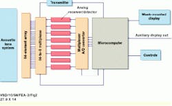
Directly behind the lens assembly is a 64-element, linear, piezoelectric transmitter/detector array (see Fig. 2). These array elements both transmit and receive sonar energy through the lens assembly, and each array element corresponds to a specific beam direction. The detector array is slightly curved for focusing in elevation, whereas the lenses focus in the x and y directions.
The 64 detector elements are multiplexed into eight transducers. All eight transducers are active simultaneously and alternately transmit to or receive signals from eight detectors at a time. Eight cycles are required for the transducers to excite/interrogate the entire 64-element array.
The transducers pass the received sonar signals through each of eight analog receiver/detector circuits. In turn, these circuits amplify and filter the signals prior to passing them on for multiplexing and insertion into four 8-bit analog-to-digital (A/D) converters. The resultant data are then loaded into 8 Mbytes of dual-port memory for access by the system`s 100-MHz Intel Corp. (Santa Clara, CA) 486-based computer.
To accurately measure the distance to the target, the computer differentiates each returned 0.3 beam over time into 512 range bins, according to the sampling rate. Therefore, the combination of beam width, range bins, and A/D conversion generates a 64 ¥ 512 ¥ 8-bit sonar image-display matrix.
The LIMIS image-update rate varies, depending upon the range increment being viewed. As explained by Belcher, because of the additional time it takes for the sound signals to travel to and back from the target, longer ranges will necessarily have lower update rates. "Maximum range scans will be updated at only 5 ft/s, while at distances from 2 to 6 ft, the scan rate can be up to 12 ft/s," says Belcher. At the system`s maximum operational range of 30 ft, images are updated at 10 ft/s. Belcher points out that although other single-beam imaging sonars, which operate by mechanically scanning the beam back and forth continuously, "work fine in relatively static viewing conditions, if either the target or the diver is moving, this time delay is unacceptable; it`s essential that the system have a rapid update rate."
Mask-mounted display
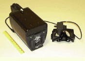
The sonar images are displayed on the diver`s head-up diver display system (HUDDS). Developed and built by the Diving and Life Support Division of the Navy`s Coastal Systems Station (Panama City, FL), the HUDDS incorporates a commercial Seiko Epson (El Segundo, CA) 0.7-in.-diagonal, color LCD display. The display and optics are housed in a roughly 1.25-in.2 ¥ 2-in.-deep package mounted on the diver`s facemask (see Fig. 3).
According to Coastal Systems Station (CSS) senior mechanical engineer Dennis Gallagher, "The Seiko device has been the "workhorse" for several prototype underwater display applications." During the course of the LIMIS program, the CSS also built several optical configurations of the LIMIS display for attachment to different facemasks. The CSS also uses a rapid-prototyping system, including a stereolithography-software design tool, which, says Gallagher, "allows us to design 3-D models of various display configurations and packages and then quickly and efficiently take the units to production."
Belcher says the HUDDS display is important for "black-water" (very-low visibility) applications, because a large conventional display on the sonar itself would not be easily viewable. Instead, "the optics in the virtual-reality-type HUDDS display gives divers the appearance that they are viewing a large-screen display, while still allowing them to maintain their situational awareness," he adds.
Displaying standard NTSC video, the HUDDS is connected to the main LIMIS unit via a `y-shaped` connector. The other fork of the connector is provided for an optional 100-ft video-uplink coaxial-cable connection that allows the system to simultaneously send a real-time video stream to a surface-monitoring station.
On-screen control
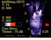
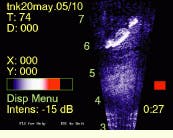
Although the sonar is transmitting and collecting sonar signal data at an oblique angle to the target, images are displayed as if viewed from above (see Fig. 4). Objects close to the sonar will appear nearer to the bottom of the display. The diver controls the system through a number of pop-up menus that he selects and manages by four thumb switches on the system handle. Although preprogrammed settings are provided, the diver can also manually adjust intensity, threshold, and gain. A small lever located between the thumb switches controls the display focus.
In addition to continually displaying basic information such as depth, water-temperature, and battery life, the diver can use the screen commands to select the viewing range and to capture and store static images in memory for later analysis. The system can store up to 50 images and their target range coordinates. An RS-232 communications (COM) port is provided for downloading the images to a PC.
Another requirement for the LIMIS was that it have a reasonable operating life. Drawing only 25 W of power (1.75 A at 14.4 V), the sonar can operate for 4 h on a single charge of its nickel-metal-hydride batteries. As pointed out by Belcher, even under relatively clear water conditions, the LIMIS`s low-power consumption offers operational advantages over standard video and lighting equipment.
Limpets located
Navy divers recently tested the LIMIS system at the Naval Amphibious Base in Little Creek, VA. As part of the test, several inert mines were prepositioned on the hull, rudder, and propeller of a landing support ship. Using the LIMIS, the divers were able to locate all the devices, including a small 3 ¥ 5 ¥ 2-in. mine hidden on the ship`s rudder.
According to Belcher, the Navy and APL are considering equipping the next-generation LIMIS system with the Swimmer In-shore Navigation System (SINS). Developed by the Coastal Systems Station, the SINS provides divers with specific tracking and position information as they move through a search area. As described by CSS`s Gallagher, the SINS was developed to give Navy Seals and other divers the ability to set up an underwater grid system within which they can swim directly to specific waypoints. A small receiver in the LIMIS detects and correlates the acoustic signals from two SINS beacons placed at fixed locations. The SINS signals are delivered to the LIMIS through its RS-232 COM port.
Belcher also sees nonmilitary applications for the LIMIS, such as aiding search-and-rescue operations by commercial diving companies that must routinely inspect underwater structures such as oil rigs and bridge footings. Another potential application is serving as the vision system for underwater remotely operated vehicles (UROVs). Here, sonar-imaging-equipped UROVs would have an advantage over conventional television-equipped systems because they must frequently operate in deep murky waters or in environments where the vehicle`s robotic arms or propulsion system would stir up debris and obscure the imagery of video cameras. Says Belcher, "Sometimes it can be a matter of hours before adequate visibility is restored for television systems, whereas the LIMIS would be unaffected."
FIGURE 1. The LIMIS acoustic lens system comprises several different lenses.
Closest to the point of transmission/reception (left) is a series of three (plastic, liquid, and plastic) lenses that form a rectangular compartment. The space between the two plastic lenses is filled with inert Fluorolube FS 5 fluid produced by Occidental Chemical Corp. (Dallas, TX). When the sonar is submerged, the cavity between the forward lens compartment and the larger lenses (right) are filled with water, which conducts the sound energy. The plano-convex lens can be moved back and forth to focus the sonar beams; these beams are then passed through the bi-concave lens onto the detector array.
Recorded from the LIMIS display, these sample "snapshot" images cover the range interval of 3 to 7 ft (top). A limpet mine is attached to the hull of a ship with a visible fuse and securing strap (bottom). The dark line of each image passing through the little finger of the diver`s hand is the result of a single dead element in the piezoelectric detector array.
FIGURE 3. The HUDDS mask-mounted display shows the charging port on the front panel (top). The acoustic lens system is housed in the upper rectangular compartment, and the electronics are placed in the lower cylindrical compartment. Note the four thumb switches and the focus control lever on the handle. The display and optics are housed in a package mounted on the diver`s facemask (bottom).


