INDUSTRIAL AUTOMATION PRODUCTS - Custom Calibration Supports Linescan System Design
Douglas Wilson
In today's automated manufacturing environments, web inspection systems check numerous products that range from the glass used in flat-panel displays to woven textiles to aluminum foil. Because these products are often wide and any defects must be measured with high accuracy, manufacturers have turned to linescan-camera-based systems to perform this task.
Multiple linescan cameras are arranged so the entire swath of the web can be imaged as the product passes under the field of view of the cameras. It may also be necessary to image both sides of the product, requiring dual multiple-linescan cameras to be deployed. In either case, the alignment and calibration of the camera systems proves a challenging task for mechanical and machine-vision engineers.
Recently, PVI Systems and APS Robotics & Integration teamed to produce a dual-sided linescan system to perform inspection on a glass-encased product. Using two arrays of four 4k × 1-pixel linescan cameras, the cameras were mounted such that both sides of the product could be imaged as it passed through the system. To ensure that the product was imaged precisely, APS Robotics & Integration was tasked with developing a camera mount that allowed each of the four cameras to be accurately aligned (see "Five degrees of freedom" below).
Custom calibration and test chart
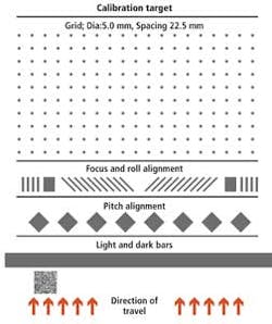
PVI Systems developed a custom test pattern that provided the image required to accurately align all eight cameras in the system. This custom-printed test pattern was used to spatially calibrate the system and each of the camera's white balance, focus, positional translation, roll, and pitch (see Fig. 1).

To spatially calibrate the system, a grid of dots with 5-mm diameter placed 22.5 mm apart in both the x and y directions was used. Here, the nominal spatial calibration in the x direction could be calculated from a priori knowledge of the camera pixel pitch and the optical magnification; spatial calibration in the y direction depends on the accuracy of the encoder that measures the motion of the web. Monitoring the x and y distances over time can provide a measure of long-term system health and determine problems such as encoder slippage or misaligned camera optics.
A number of vertical bars and chevrons on the custom test chart help to focus each of the cameras and obtain an accurate angular and translational alignment. Contrast detection autofocus is used to perform autofocusing (see "Phase detection speeds camera autofocusing," in this issue for more information on autofocus methods). This compares the contrast of adjacent pixels along a line. While blurred images form a Gaussian curve, a theoretically perfectly sharp intensity image profile will more rapidly transition from black to white. The image is in best focus at the adjustment point at which the contrast-based focus figure of merit (FOM) is at a maximum. In most cases, the focus FOM curve is a bell-shaped curve with the central peak being the best focus.
By forming these vertical bars of different widths, it is also possible to automatically measure the offset along the axis of the linescan camera (x-axis). Edge detection methods, including sub-pixel measurement provides the x-offset measurement data needed to adjust the cameras. This adjustment is used to position the cameras relative to each other and the external absolute coordinate system. External alignment to the external coordinate system ensures that each of the cameras images the correct swath (in the x direction) of the web.
Calibrating the camera system
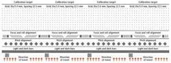
Four test images are included in the calibration target so the four cameras view overlapping vertical bars (see Fig. 2). Measuring the position of these different stripes relative to the edge of the camera boundary then provides the x-axis translation between the cameras. A precise mechanical adjustment can be made to allow the camera images to be aligned along the x-axis with single-pixel accuracy. Once the y-axis translation and roll and pitch compensation are completed, the images from the cameras can be stitched together without any image processing by simply concatenating the individual line scans from all the cameras.
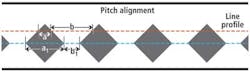
To accurately adjust the pitch of each of the cameras, the test target incorporates an array of diamond patterns. The edges of the diamonds are measured using a line profile through the patterns of diamonds. The camera's pitch is adjusted until the distance measured across the individual diamonds is maximized and/or the distance between each of the diamonds is minimized (see Fig. 3).
Camera-to-camera roll and lighting misalignment produce image-quality degradation. The relative roll prevents direct stitching to form the composite images since the cameras are not in a straight line on the object plane. Roll error relative to the lighting creates an unevenly illuminated image. In cases of extreme roll error, it is even possible to have some of the pixels capture nonilluminated portions of the image. To allow compensation of any camera roll (or alignment error in the x-y plane), a series of chevrons at 45° angles were placed between these vertical bars (see Fig. 4). Only two chevrons are required, but additional pairs were included to enable averaging of the results.
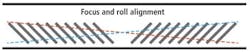
As the roll angle of a camera increases or decreases from ideal, so too will the distance measured between the chevrons. Such a positive or negative roll angle will have an opposite effect on the distance measured between the second set of chevrons, since they are placed at an angle 90° from the first. The difference between the left and right leaning measurements is a direct measure of the roll error. The roll error computed using this method is linear to the roll angle and a signed quantity that allows instantaneous analysis of which direction to adjust the camera to correct the error.
To perform flat-field lighting and defective-pixel correction across the linear array, the system analyzes an array of light bars incorporated into the test chart. Because the test target is of uniform brightness, any lighting variation across the imager can be estimated and used to both flatten the field and compensate for any nonuniform pixel gains in the camera array. By performing this analysis across the entire four-camera system, more accurate (evenly lit) images could be obtained, improving grayscale threshold detection performance with less image processing. In the PVI system, the corrections were stored in the individual Teledyne DALSA cameras so the acquired images were delivered to the processing system fully corrected.
A given calibration target can have additional features added beyond those already described. PVI Systems included information about the calibration target, such as the grid dot size and spacing, in a 2-D QR code. In an early design concept, the target incorporated resolution features that were adapted from the USAF 1951 test target and simulated defects. In the final design, however, it was found that these features were not required, and so were not implemented.
To allow the customer to rapidly calibrate the linescan system, PVI Systems also developed a graphical user interface (GUI) that guides the user step by step through the calibration procedure. After setting the lighting, focus, roll, and camera pitch are performed followed by flat-field and defective-pixel correction and spatial calibration, a process that the customer used to align the system in less than 30 min.
Douglas Wilson is president of PVI Systems (Niantic, CT, USA).
Five degrees of freedom
Using the test chart developed by PVI Systems, each camera could be adjusted such that the linescan image captured by each individual camera accurately aligned to the next. A mechanical system based on slides, gimbals, and jackscrews allowed each camera to be adjusted with five degrees of freedom (see figure).
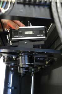
These five degrees of freedom—x, y, z (to alter the focal distance), pitch, and roll—all needed to be independently adjusted to ensure multiple-camera alignment. All four cameras of each array were mounted on a rigid frame that spanned the width of the machine so each camera could capture 1/4 of the product's 5-ft width at a distance of 25 in. from the product. These array frames were then positioned (in the z direction) by jackscrews that were adjusted using a hex key.
First, to achieve even spacing across the width of the product (the x direction) while maintaining the scan axis of the cameras, each camera was placed in its own independently adjustable mount mechanism. These camera mounts were keyed to the array frame so each could move laterally across the width of the machine while maintaining its orientation to the product.
Next, to align the scan lines of each of the four cameras, each of these camera mounts was also keyed at 90° to the array frame (the y direction) and moved to the proper position with a trapped jackscrew. While this allowed the cameras to be aligned in the x-y plane, it could not solely be used to align the scan lines since any rotation or roll of the camera in the x-z plane would also result in misalignment of the scan lines.
Finally, to provide the last two degrees of freedom, each camera was placed in a cradle that was allowed to move in pitch (the y-z plane) and roll (about the optical axis of the camera). Thus, any reflected light captured across each of the 4k × 1-pixel CCD elements in each of the cameras would be at the peak of the light intensity profile across the web.
—Charles "Chuck" Chadwick is president of APS Robotics & Integration (Deep River, CT, USA).
Company Info
APS Robotics & Integration, Deep River, CT, USA
PVI Systems, Niantic, CT, USA
Teledyne DALSA, Waterloo, ON, USA