Vision System Tracks Trouble with Trains
Kambiz Nayebi
Many machine-vision systems operate under controlled environments in factory settings. However, designers of systems for the transportation industry are faced with bigger challenges: These systems must capture images of vehicles traveling at different speeds in varying weather conditions and over wide temperature ranges.
Developing transportation imaging systems requires extensive modification of off-the-shelf components such as cameras and lighting. Custom heating, cooling, and cleaning systems must be created to enable reliable operation of the vision system over long periods of time in harsh outdoor environments. Custom software is also needed for each application because existing libraries of image-processing software fail to deliver the necessary performance.
Nowhere is this more obvious than in the design of automatic wayside inspection systems for the railroad industry. Working in harsh, remote environments, these systems must inspect mechanical components found on the rolling stock of freight and passenger trains. This allows them to assess the trains' safety and alert operators of any maintenance that might be required.
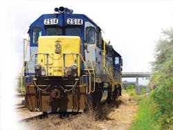
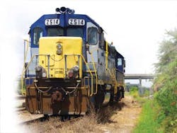
Based on its experience developing a number of individual custom systems to inspect train wheels, brakes, couplers, ladders, and handholds on the sides of freight trains, Beena Vision Systems has introduced a train inspection system called TrainView to examine multiple train components.
The hardware and software of each TrainView system are customized to meet the needs of both the railroad operator and the environment in which it must operate. One such TrainView system (see Fig. 1) comprises a number of cameras from Teledyne DALSA and Basler placed between the tracks of the railroad and supported on two upright sections of a tower and on a horizontal crossbeam between the two that spans the width of the track. In doing so, the system can capture images of over 160 key components underneath the train, on its sides and roof.
Seeing from all sides now
In this system, nine Teledyne DALSA Spyder SG-14-02K80 linescan cameras and an industrial LED lighting system are housed within a steel tie structure installed under the track to image the underside of the train (see Fig. 2a).
Three of the nine cameras capture images of the couplers and coupler pin plates that connect the rolling stock (see Fig. 2b). An automatic analysis of the plates determines which ones are damaged or defective. More specifically, images are analyzed for possible plate deformation, displacement, and missing fasteners such as bolts (see Fig. 2c).
The other six cameras image the center sill—the main structural element that carries the loads of an individual car—and the body side sills that run along the end and sides of the underframe to provide structural integrity to the car and reinforce the center sill.
One of the major tasks of these cameras is to capture images of the brake rigging components from which their condition can be determined. Images are analyzed by an algorithm that detects the brake beams, levers, pins, and cotters keys for these pins to ensure the major brake rigging components do exist and are healthy.
After identifying a specific brake rigging component, the algorithm classifies it into one of many possible different types; there are more than six different brake riggings types that are identified by the system first. Then the detected subcomponents are analyzed for defects. Defects can be missing critical parts like a bolt, a nut, or a pin; bent or displaced elements; or shiny components indicating unnecessary contact between components.
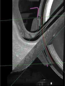
On each of the twin towers on the TrainView system, three Basler Runner ruL2048 linescan cameras capture images of key components on the side of the train. Specifically, two pairs of cameras image the parts of the bogie suspension components such as springs and friction shoes. Here, the system determines the brake shoe existence and measures its thickness and condition. Loose brake shoes as a result of a displaced brake-shoe key are also identified (see Fig. 3).
The third camera mounted on each side of the towers captures images of the components that are attached to the sides of the railroad cars. These so-called safety appliances, which include ladders and walkways attached to the body of the freight car, are required by federal law to be kept in a usable condition through a continuous monitoring program—if not, the railroad companies are fined (see Fig. 4).
A part of the system referred to as WheelView is capable of inspecting the condition of the train wheels. Because the train wheels are exposed to high mechanical stresses during use that lead to friction-related wear, inspecting them regularly is vital. WheelView uses two laser scanners and two cameras to capture a complete 3-D profile of each of the wheels. From the data, the flange height, width, and slope; the thickness of the rim; and the tread wear of each wheel can be determined.
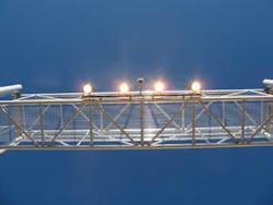
The sole Basler Runner ruL2048 camera along the crossbeam of the tower structure allows the system to capture images of the top of the railroad cars. This camera images the equipment that is installed on the roof of the car such as roof-top hatches, walkways, and handles. The camera also detects whether there are any loads present inside the open-top cars (see Fig. 5).
Illumination, imaging, and inspection
Providing the lighting to illuminate the train as it passes the cameras is a significant challenge. Unlike a machine-vision application where the distance of an object from the camera is constant, objects on the train to be imaged are presented to the system over a range of distances. To enable the cameras to capture images under these conditions over a wide depth of field, the system uses high-power industrial LED lighting from Larson Electronics Magnalight that produce a high-intensity, 0.5–1-m band of light across the train.
Both the cameras and enclosures in which they reside are customized to withstand shock, vibration, and changing climatic conditions. The cameras are all rebuilt with shock-resistant components such as screws and bolts, while standard lenses are replaced with ruggedized versions. The cameras and lighting components are installed in shock-isolated enclosures that are temperature controlled via cooling and heating systems.
The enclosure that houses the linescan cameras mounted on the track is especially prone to environmental effects; rain and snow, grease, oil, and debris may fall from underneath the train or be blown onto it from around the tracks. To enable the cameras to operate maintenance free over a long period of time, a low-pressure heated air supply is blown through holes in shutters on the enclosure, opening them up prior to the arrival of the train to enable the cameras to capture a clean image of the underside of the train.
As a train approaches the TrainView system, induction-based sensors detect the position of the train wheel to trigger the acquisition process. Having captured the images of a train as it moves past the inspection station at speeds up to 140 km/hr, data from the linescan cameras are transferred over a GigE interface to a number of servers that reside in an enclosure by the side of the track.
The servers first preprocess the images to enhance them and compensate for environmental effects. After image rectification and stitching, edge and texture detection and analysis is performed on the images. Rule-based or learning-based pattern matching and classification methods are then employed to find specific components. Custom algorithms extract the key features from each image to identify the position and orientation of specific shapes and determine their measurements, after which they are classified as defective or healthy.
Should the system identify any missing, defective, or out-of-tolerance components on the train, it can deliver a message—together with the appropriate documentation detailing the nature of the failure—to the railroad company either via e-mail or SMS message. In the case of a critical failure, the train company can choose to immediately halt the train, or in the case of a noncritical failure, the company can schedule a time for maintenance.
Through the identification of key safety components using vision-based inspection, railroad companies can monitor their rolling stock to prevent accidents such as derailments. In addition, wear on specific components can be identified so they may be replaced appropriately, keeping maintenance costs to a minimum.
features, advantages, benefits
Since vision systems that inspect transportation systems may be called upon to perform a variety of operations, no one system is alike. Before any algorithm development, the system's working environment must be carefully considered and the components of the system built to meet specific climatic conditions.
The features and tolerances of the parts that are of interest to a railroad company—such as wheels or brakes—must be determined, after which images must be acquired of the components. The nature of the components to be imaged on a train can vary dramatically—especially from country to country. In many systems, all the code is custom written in C++ to perform the image-processing tasks for each application.
Wheel inspection is one of the few areas where it is possible to reuse or adapt previous software, but only because most railroad wheels have similar profiles. Here, software developers can call upon a library of numerous in-house algorithms that can be modified to meet the needs of a particular user.
Kambiz Nayebi, PhD, is president of Beena Vision Systems (Roswell, GA, USA).
Company Info
Basler
Ahrensburg, Germany
Larson Electronics Magnalight
Kemp, TX, USA
Teledyne DALSA
Waterloo, ON, Canada


