Machine-Vision Needs Change with Color Imaging: Part II


In machine-vision applications, it is important to understand the characteristics of color spaces and choose the one that will yield the most effective results.
Which color space to choose is application specific and depends on how precisely a system is required to discern one color from another. For example,a process where objects need to be sorted according to their color has very different requirements than a color-matching application, which involves identifying a specific shade of a color in an image.
The best color space to use for making measurements of the visual differences between objects is one that is both perceptually uniform and device independent. In a perceptually uniform system, the mathematical distance between colors in the color model is proportional to the perceived difference between the colors. In a device-independent system, the color coordinates of an object that are characterized by one imaging device will be the same as the coordinates characterized by another.
Digital cameras that employ CMOS or CCD image sensors captureRGB values of an image. These can be processed in RGB color space: an additive color space in which the dominant colors of the primaries red, green, and blue are added together to reproduce an array of colors.
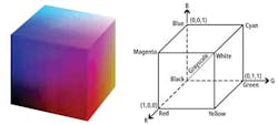
However, RGB is a device-dependent color model, and different devices such as cameras will detect or reproduce a given RGB value differently because the image sensors employed vary from manufacturer to manufacturer. Neither is the RGB color space perceptually uniform, a fact that can be visualized by mapping the RGB color space to a cube (see Fig. 1). Hence, while processing colors in RGB space can determine the differences between colors, it is more difficult to separate shades of the same color.
There are other ways of classifying colors that correspond more closely to how color is perceived by the human eye. One such system was developed by Professor Albert Munsell in the first decade of the 20th century. In the Munsell color model, color vales are described by their hue, chroma, and lightness.
Perceptually uniform
Strongly influenced by the Munsell color system, theCIE L*a*b* and the CIE Luv color spaces are two other widely used color spaces in machine vision. These color spaces are more perceptually uniform than the RGB space. In the case of CIE L*a*b* (and also CIE Luv), color differences are expressed as distances between two color coordinates in a three-dimensional color space. Equal distances in the color space represent the same color differences perceived by a human being.
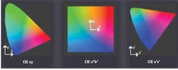
CIE Luv distributes colors roughly proportional to their perceived color difference. Hence, a region that is twice as large in its u and v components appears to have twice the color diversity. CIE L*a*b* remaps the visible colors so that they extend equally on two axes. Each axis in the CIE L*a*b* color space also represents an easily recognizable property of the colors, such as their red-green and blue-yellow shifts (see Fig. 2).
When a color is expressed in CIE L*a*b* color space, L defines the lightness of the color, a* denotes the red/green value, and b* represents the yellow/blue value. Figure 3 shows a color wheel that illustrates the principle. Moving in the +a* direction, colors will become redder, while a movement in the +b* direction represents a shift toward yellow. The central L* axis represents the white content of a color.

Although color cameras return RGB values, the images from them can be converted into CIE spaces for processing. In the device-independent, perceptually uniform CIE L*a*b* or CIE Luv color spaces, the differences between the coordinates of two different colors almost correspond to the perceived difference between two colors. Therefore, manipulating images in the CIE L*a*b* color space is a useful way to characterize colored surfaces.
Bottle caps: An example
To demonstrate the differences between processing an image in the RGB space and the CIE L*a*b* space, an image of nine colored bottle caps was captured by a standard industrial RGB camera (see Fig. 4a). Along the top of the image are three caps: a rose- or raspberry-colored cap, a peach-colored cap, and a grayish cap. To the human eye, the cap that might be considered to have the greatest red component would be the rose-colored cap. In the RGB space, however, that cap has a red value of 152, while the peach-colored cap has a value of 207, and the third grayish cap a value of 169.
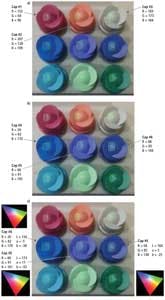
The surprising result is that the one that looks most red to the human eye has the lowest R value. The reason for this is that caps two and three are reflecting more light, so their overall RGB numbers are all higher because the imager in the digital camera is measuring the light intensity falling onto it.
Similarly, if the values of the blue colors of the caps in the second line of the image are measured (see Fig. 4b), the first has a value of 170, the second a value of 191, and the third a blue component of 148. Clearly, then, because the blue values of the caps in RGB space are so close, it may be difficult to distinguish between them if the images were to be processed in RGB space.
By processing the images in CIE L*a*b* space, the task becomes easier (see Fig. 4c). In the CIE L*a*b* space, the first cap on the second row has an L* value of 156, an a* value of -5, and a b* value of -38. The second cap on the second row has an L* value of 173, a* is +11, and b* is -33. The third cap has an L* value of 164, a* is 5, and b* is -25.
Looking at where these values places each of the caps in the CIE L*a*b* color space, it becomes clear that it is easier to differentiate the first cap in the line from the other two, which may not be as straightforward in RGB space.
Differentiating colors
One of the measurements frequently used in CIE L*a*b* space to differentiate between colors is called the Delta-E (dE). This is calculated by finding the square root of the sum of the squares of the L*, a*, and b* values of one color and subtracting sum of the squares of the L*, a*, and b* values of another. As such, it represents a single number that can be used as a measure of the "distance" between two colors.
However, system integrators should be aware that the type of lighting chosen for a specific application can have a profound effect on the dE numbers calculated by the image-processing software, and thus how effectively a system can differentiate between colors.
For example, when three different paint samples were illuminated by an LED light source, their CIE L*a*b* numbers -- and thus the dE numbers that differentiate them -- vary only slightly. When illuminated under a quartz-halogen light source, however, the dE differences are larger as the shades of the samples are more clearly defined.
When attempting to differentiate between different shades of color, it may be worth considering processing the color images in CIE L*a*b* rather than RGB color space. Of equal importance, however, is the role lighting plays in enabling the system software to differentiate shades of similar colors.
_____________________________________________________________________
When monochrome will suffice
Before choosing any color camera to address a specific image-processing application, it is important to evaluate whether the inspection task could be performed with a monochrome camera equipped with color filters.
As an example of how this might be accomplished in practice, consider the Maxwell triangle shown in Fig. 1a. Here, each of the three primary colors -- red, green, and blue -- is located at a corner of the triangle. The white color is in the middle. Other colors, such as cyan, magenta, and yellow, are formed by a combination of the RGB components depending on their distances from each of the three sides of the triangle.
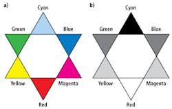
Figure 1b illustrates the effect of imaging the Maxwell color chart with a monochrome camera equipped with a red filter. As white light passes through the red filter, it absorbs all the colors of the light spectrum with the exception of red. Hence, the red part of any image appears as a bright white, while the cyan part of the image appears black. The other colors will vary in intensity according to the amount of red present.
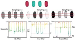
By using such filtering techniques, it is possible to design simple monochrome vision systems to inspect colored objects. Figure 2 shows how color filters can be used to determine the presence of red and green pills in a blister pack. Whereas it is impossible to discern the difference between the two pills without a filter, a red or green filter will enable the differences to be clear.
However, applications are rarely this straightforward. Many vision systems must also be flexible enough so that any changes to a production process, or the product to be inspected, can be accommodated. Nevertheless, in simpler applications, it is worth considering whether a monochrome system might prove to be a more cost-effective alternative to a color camera.