3D-vision-guided robot automates battery production process
In 2018, the Norwegian Parliament passed legislation outlawing harmful emissions from ferries and cruisers operating in the country’s fjords, with full compliance expected by 2026. This initiative increased the demand for maritime batteries to power electric propulsion systems, the type of batteries produced at a Siemens (Munich, Germany; www.siemens.com) automated production facility in Trondheim, engineered by system integrator Intek Engineering AS (Raufoss, Norway; www.intek.no).
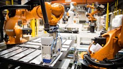
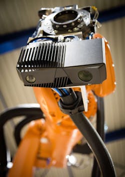
The factory’s automated depalletization cell utilizes a Zivid (Oslo, Norway; www.zivid.com) One 3D camera, mounted on a Kuka (Augsburg, Germany; www.kuka.com) KR 09 robot arm featuring a custom-designed vacuum gripper. The factory-calibrated camera uses structured light technology to capture RGB color, 2D, and 3D images at 2.3 MPixel resolution (1920 x 1200) and 12 exposures per 3D frame, and features USB 3.0 interface.
“There were no comparable 3D sensors available when we were designing this production cell,” says Olaf Pedersen, Project Manager at Intek. “What made us choose the Zivid One was price and performance, speed and data quality.”
The camera connects to an industrial PC with Intel (Santa Clara, CA, USA; www.intel.com) i7 processor and NVIDIA (Santa Clara, CA, USA; www.nvidia.com) GPU, which also issues movement commands to the robot arm via TCP/IP over USB3 connection.
Related: 3D scanners measure and inspect aerospace turbine blades
One of three different varieties of parts, pre-stacked onto pallets by suppliers, arrive at the depalletization cell on a forklift or pallet jack operated by a human employee. Some of the parts rest in cardboard separators while blister packs contain other part types.
A human operator pauses the depalletization cell via a cycle stop button or on the system’s HMI, a Siemens OP TP1900 operator panel, in order to place the pallet into position. When the system restarts, the 3D camera conducts an initial scan to determine the exact position of the pallet and the height of the parts stack on top of the pallet. This scan determines the optimal position for the robot arm to move the 3D camera for a second, more detailed scan.
Software custom-designed by Intek uses rules-based algorithms to analyze the 3D point cloud data, looking for repeated patterns of planes, edges, circles, and other, very basic features, which allows the software to identify the types of parts on the pallet.
Intek chose a 3D solution rather than a 2D solution because the latter is more sensitive to light and requires very accurate position with regard to camera distance from the products, says Pedersen. While 2D hardware costs less than 3D hardware, engineering a 2D solution that could handle a variety of different product types required a larger number of commissioning hours, adds Pedersen.
Once the software identifies the specific type of part and the pattern in which the parts are arranged on the pallet, the pick and place routine begins. A SICK (Düsseldorf, Germany; www.sick.com) W12 photoelectric sensor, connected to the robot I/O, verifies each pick. An alarm triggers and the system automatically pauses if the sensor does not register a pick . The operator must refer to the HMI to determine the problem and correct the situation. The software is robust enough that these sorts of issues rarely occur, says Pedersen.
Once the operator corrects the issue and restarts the depalletization cell, a new 3D initialization scan takes place, and the pick and place routine continues. The state-based system, designed to remember previous interactions, remembers the position of the missed pick and makes another attempt.
If a pick falls because of a damaged part, the operator can designate the part as damaged in the HMI and then remove the damaged part. When the cell begins again, the software registers the damage part as picked and moves on to the next part.
Related: 3D laser profiler inspects cosmetics
The picked parts are placed onto a special custom-made workpiece pallet on top of an Omron (Shimogyo-Ku, Kyoto, Japan; www.omron.com) LD-90 autonomous mobile robot (AMR). Each part has its own position on the workpiece pallet, while some positions accommodate different part types. A Siemens RFID reader scans the workpiece pallet when it arrives at the cell to confirm the pallet is the correct type to accommodate the parts being depalletized.
After the robot places each part on the workpiece pallet, the RFID code reader sends the data to the facility’s master control system. When depalletization completes, the workpiece pallet state changes to ready for transport and the control system issues a move order to the AMR. Seventy parts must leave the production cell on an AMR every 7.5 minutes for the cell to provide parts fast enough to allow the rest of the line to operate at normal speed.
About the Author

Dennis Scimeca
Dennis Scimeca is a veteran technology journalist with expertise in interactive entertainment and virtual reality. At Vision Systems Design, Dennis covered machine vision and image processing with an eye toward leading-edge technologies and practical applications for making a better world. Currently, he is the senior editor for technology at IndustryWeek, a partner publication to Vision Systems Design.