Stereo System
A 3-D imaging system replaces four cameras for inspecting automotive engine parts
Nemak, a manufacturer of aluminum cylinder heads and engine blocks for the automotive industry, decided to update its system after nearly eight years of operating its Breather Core 2-D gray-scale inspection system. Breather cores are compressed sand. Aluminum is poured over the sand to create the engine parts.
Because the environment surrounding a hydraulic press is less hazardous than around molten aluminum, it is better to inspect the cores rather than the aluminum parts. So, Nemak issued an RFP to replace its four-camera, 2-D gray-scale vision system with a similar system.
“Nemak contacted us and said it was time to update their breather inspection system,” explains Dean Scarlett, vice president of vision integrator Vista Solutions. “Other groups were specifying the latest cameras in another four-camera configuration. We said that we were declining to quote because we wanted them to look at different solutions.”
Vista Solutions suggested that a 3-D imaging system using laser triangulation could provide a more accurate inspection system at a fraction of the cost. The system could detect defects significantly smaller than those previously inspected and at 60% of the cost, replacing the existing four-camera gray-scale vision system.

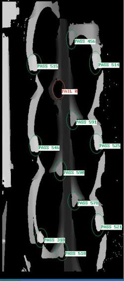
Vista Solutions had recently achieved authorized integrator status with SICK, maker of the IVC-3D integrated vision camera with laser triangulation. Scarlett says, “We told Nemak that if it really wanted to inspect this core, it needed volumetric defect information and not just area. So we obtained some core samples and knew as soon as we’d seen a screenshot that this was the right way to approach the problem (see Fig. 1). We set it up on our own robot, worked through the problems and algorithms associated with inspection, and Nemak virtually committed to giving us the order on the spot.”
A better vision
The previous core-inspection system used four analog cameras (8 to 10 years old) to capture four images that reveal 12 breather tabs on one side of core. Under this system, a robot would extract the core from the forming press, position the core in front of the cameras, stop for a second while the images were collected, and then pass the part to a reject conveyor or on to another conveyor leading to the aluminum casting line, depending on whether the core failed or passed, respectively. Because the robot had to stop the core in front of the cameras, the inspection routine injected a few extra seconds into the core production line while the ABB six-axis robot decelerated, stopped, and accelerated again.
Each breather tab is approximately a centimeter in diameter by a couple of centimeters tall. The Nemak manufacturing process only requires that a majority of the tab be present to result in a good aluminum part. The older system—and the rest of the proposals to Nemak—suggested upgrading camera technology and staying with gray-scale imaging and geometric pattern searches to identify key features indicating the presence of a breather tab.
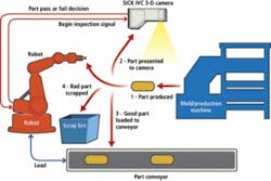
The Vista Solutions system also uses a static inspection station served by an ABB robot. A SICK IVC-3D 200 camera was mounted just to the side of the robot path. The camera holds a CMOS sensor offering a maximum profile width of 1024 pixels and a red diode-laser line generator in a single housing. A laser line is directed straight at the object under test, while the CMOS camera is placed slightly off the optical axis. In this configuration, differences in height are indicated by displacement of the laser line in the acquired image (see Fig. 2).

A bandpass filter placed under the IVC-3D 200 protective window filters out wavelengths other than those emitted by the laser line generator. This reduces the need for additional vision-specific lighting and reduces the footprint and bill of materials for the vision system.
The camera also houses an 800-MHz microprocessor with FPGA acceleration. This gives designers the ability to process the images completely at the camera head using a SICK IVC Studio object-based image processing library or to send the entire image to a separate processing station.
Once the system is powered on and the robot retrieves the first breather core from the mold, the robot controller sends a query signal across a relay to one of the IVC-3D 200’s six programmable I/O ports. If the system is ready for inspection, a trigger signal is sent back to the robot controller, and the robot takes the core from the press and moves across the camera’s 200 × 600-mm field of view at a standoff distance that allows the full width of the core to be acquired from a single image (see Fig. 3).
According to Keith DeGroot, Vista Solutions manager of application engineering, one important consideration in the system design was whether or not to use an encoder to track the position of the core as it moved in front of the camera. “We determined that the ABB robot could pass the part at a constant speed in front of the camera, so we could use timing to create the 3-D surface map rather than physical position using an encoder,” DeGroot says.
The camera builds a 3-D surface map by combining “profiles”—individual images that reveal the position of the laser line. The camera collects the profiles at rates up to 5000/s, processing them in real time on the FPGA and microprocessor and stacking them into a continuous 3-D surface map of the core’s surface, where height is displayed as intensity, in the case of gray-scale display, or color, in the case of false-color surface-map display.
In addition to the six programmable discreet I/O ports, the IVC-3D 200 also offers an RS-422 interface for encoders and an RS-485 output for PLC communication, which was not needed in this case because the ABB robot is already in the workcell. However, the camera does include a 10/100 Ethernet port and internal Web server. DeGroot was able to connect the IVC-3D 200 to the plant’s LAN and set up the camera to store result data and images on the network’s FTP server for remote viewing by plant personnel and debugging by Vista Solutions, if necessary.
“We can save images on the plant network, but we typically save text files,” explains DeGroot. “We can dial up the IP of the camera and view the latest images and results for each task. We program the camera by taking a laptop to the camera and uploading the program developed in IVC Studio.”
Moving to a scanning-mode application required a slight reprogramming of the ABB robot, since it no longer needed to present the part to the inspection station; however, this allowed the robot to take a straight path from the press to the output conveyor, saving a small amount of time. “While the throughput improvement wasn’t significant for the forming operation, it did give a little more time for other actions down the production line, easing their constraints,” Scarlett adds.
Although the combination of optics, camera field of view, and size of the core established a minimum spatial resolution of 0.2 mm for inspecting the breather tabs, Nemak officials ‘tweaked’ the threshold to catch larger defects in the tab structure, which improved the system’s throughput. Tests of the SICK system showed a total effectiveness of 98.17% on 10 parts—four with known faults and six good parts. None of the errors allowed failed parts to pass. Similar gray-scale systems generated 85% effectiveness and passed known faulty parts.

Features, advantages, benefits

“From the initial installation to the trial verifications it was apparent that the 3-D system had a lot to offer, with an overall average effectiveness of 97.7% in scrap-detection rate compared to an overall average effectiveness of 85% in scrap-detection rate with the 2-D system,” says Mandy Karnib, base plant lean manufacturing coordinator at the Nemak Windsor plant.
“During our trials with the 3-D system the false trials were attributed to multiple handling of the parts that caused them to fail on their third trial. In short, the 3-D laser system has been extremely beneficial in allowing us to significantly reduce our breather-core scrap both internally and externally.”