Moiré imaging methods enhance 3D image generation in machine vision
Novel 3D technique creates topographic maps to highlight changes in surface slope or curvature.
Kevin Harding
It has often been said that using the right lighting can make or break a machine vision application. Low-angle lighting might bring out surface textures or useful shadows, back lighting provides a clean part outline, and polarization filters can reduce unwanted glare. These are all well-known and widely used tools that have been around for decades.
The higher end of such tools involves 3D methods, but this comes at the expense of more component complexity, often more time to collect good data, and certainly more data to analyze. For many applications, full 3D data is not really needed, but something more than a 2D image with a greyscale image of the surface could be of great value.
For example, an image of a cast metal part typically provides little information about surface features. The edges of any structures beyond the outline may provide poor definition. Any light variation due to surface shape may be lost in surface brightness variations from surface texture, graphite dust, or grease on the part.
Many systems may deploy laser line sensors or 3D structured lighting systems, but one possible tool that has been around for a long time— but rarely used—is moiré patterns.
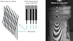
Moiré patterns are created by the interference of two grating patterns. A subject grating is created by projecting, shadowing, or contacting a grating onto the object to be measured and comparing this grating to some reference grating by overlaying the two grating images. In the case of contouring (Figure 1), the grating is viewed from a different angle than from which it has been projected or shadowed onto the part, thus creating a triangulation effect. If the reference grating is a straight line grating, the beat pattern between the two gratings forms a contour map of the object’s surface in the same way that a topographic map delineates the contours of the land.
The interpretation of moiré contouring is visually simple. A tilt of an object produces evenly spaced lines, whereas a bend or twist shows variable spacing. The orientation and spacing of the moiré lines or fringes are purely a function of the subject’s shape, and not of the orientation of the lines (Figure 2). Moiré contouring takes the effect of a line of light gage which projects a line onto a part at an angle and extends the effect to provide a degree of preprocessing within the optical system.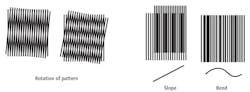
This moiré effect also serves to leverage the sensitivity of the pattern by taking a very small displacement of a line and amplifying the effect such that it can easily be seen. Many optical glass scale measuring systems use a moiré pattern between two such gratings, as it is much easier to see and measure the large moiré “beat” pattern than to resolve the movement of a very small grating line.
For a 3D measurement, this moiré pattern allows measurements of small variations in the part shape that, for a simple structured light system, is below the resolution limit of the camera or sensor and thus unmeasurable. As an enhancement tool, the moiré pattern produces an intuitive pattern on gently curving part surfaces, enhancing features otherwise invisible to most simple directional lighting methods and creating a pattern that can be interpreted quantitatively using basic tools such as edge detectors and pattern matching found in many smart cameras.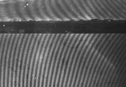
Using this moiré effect to see small defects due to dents, curvature variation, or curvature orientation on the surface of an object does not require the generation of a 3D map with millions of points of data to be interpreted. In looking at a part with a line pattern projected or attached to the part through another grating, a change in the orientation of the pattern on the part relative to the reference grating (Figure 3) is seen, indicating slope or orientation of the surface and the presence of any anomalies such as a dent on that surface. A pattern is seen here, because of the change of line spacing and tilts related to the shape of the part that is more like a topographic map rather than some complicated line pattern that must be fit to a mathematical surface before using the information.
Unlike a simple structured light pattern, with moiré contour lines, the contour effect of the pattern moves with the part. By comparing the moiré pattern of a reference part deemed correct with a part under test, subtracting out the consistent shape of the part from the moiré pattern seen using pattern matching tools, and leaving only information about changes in the surface shape of the part, is possible. In applying a label to the bottle (Figure 2), seeing the wrinkle in the label is possible without the need to first fit the data to the shape of the bottle and perform complex 3D comparisons on a million points. Figure 4 shows a moiré pattern from two gratings applied to the surface of a flat part. The reference to generate the moiré is a simple straight-line grating. The change in orientation of the lines is due to an angle difference of only a couple degrees between the two applied gratings.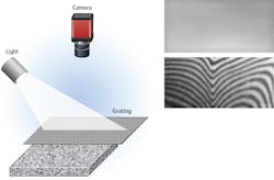
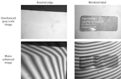
Figure 6 shows a beveled edge and a wrinkled label with and without the moiré effect. By finding the angle change of the moiré lines the bevel can be measured, or the wrinkle recognized, using simple edge angle tools available in many smart cameras.
A more dramatic example is shown in Figure 7 where a 2-inch-diameter area is recessed about 0.25 inches below the top surface of a part, but is out of parallel by a few thousandths of an inch. This parallelism error is only about a tenth of a degree of the recessed area relative to the top surface, but the small change in the angle of the lines makes this parallelism error evident.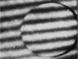
The only measurement needed to see a change in angle involves counting the number of lines across a given area of a plane. If each moiré line indicates a change in distance of 0.02 inches (the resolution in Figure 6), then a change of one fringe line on one surface compared to another over 4 inches means a change of about 4.5°. Seeing changes of less than a degree is realistic over areas of an inch or more.
Figure 8 shows two holes with tapers of 30° and 45°. Using a moiré-enhanced image enables the identification of which taper was used by counting the lines from the hole center to edge.
As moiré can highlight a very small change in the depth on a part relative to the area of view, checking for dents on a larger sheet metal panel of 4 to 6 feet in size can be greatly simplified by a moiré enhancement. This image (bit.ly/VSD-CAR) shows a car door covering about a 4-foot-wide area. The dent on the lower right is about 0.004 inches deep. Though difficult to see by eye—or even feel—the reflection from that spot shows up as a potentially-objectionable dent to the customer once a high-gloss paint is applied to the car.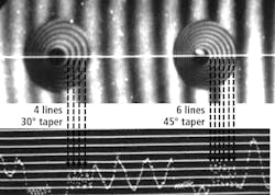
Conclusion
There are many machine vision applications where the critical factor involves measuring a feature relative to a beveled edge, lining up two surfaces to each other for welding, or sorting tapered parts. Moiré imaging methods enable topographic map creation, visually highlighting changes in surface slope or curvature usable with standard vision tools such as edge counting or spacing, without needing to produce a full 3D surface map. With this highlighting, smart cameras can inspect shape features without the need for full solid models and extensive programming efforts.
Kevin Harding, Partner, Optical Metrology Solutions LLC (Niskayuna, NY, USA; www.opticalmetrologysolutions.com)