Smart vision system ensures 100% cylinder bore inspection
Machine vision and deep learning technologies help to automate bore cylinder coating inspection process.
As the main part of a combustion engine, cast cylinder blocks act as support for the complete engine structure and consist of several holes called bores in which components are mounted. One of the larger-diameter bores in the block are those in which the pistons will eventually be mounted. When placed in these bores, the pistons carry thrust through connecting rods to the crankshaft.
In the past, a cylinder lining was placed inside the cast cylinder blocks to house the pistons. This resulted in heavier engines with smaller bores. Today, however, this process has been eliminated thanks to the deployment of Plasma Transfer Wire Arc (PTWA) technology, a technique invented by Flame-Spray Industries (Port Washington, NY, USA;http://flame-spray.net).
In the PTWA process, a wear-resistant coating is sprayed onto the internal surface of the engine block cylinder bores. This eliminates the need for cylinder linings while at the same time giving the engine a larger bore size, such that larger intake valves can be used, making the engine more powerful.
“After this iron coating is applied,” says Ahmad Shawky, Lead Vision Specialist with industrial automation specialist and systems integration company AIS Technologies Group (Windsor, ON, Canada;www.aistechgroup.com), “the cylinder bore must be examined to ensure that it has been coated evenly by the PTWA process.”
Since PTWA technology can leave deposits of coating material (or “spits”) on the inside walls of the cylinder, these must be inspected to ensure that the number, width, length, and position of any spits is within the tolerance set by the manufacturer.
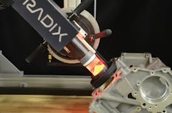
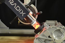
Figure 1: One of the configurations of the AIS Technologies Group’s cylinder coating inspection system makes use of a custom secondary optic to image the vertical walls of an object.
Before the introduction and deployment of machine vision systems to accomplish this task, single-engine blocks were taken from the production line—perhaps one every shift—and cut open to inspect the inside walls of the cylinder bores for spits.
Related:3D imaging enables high-speed bore inspection
“Needless to say,” says Shawky, “this was a time consuming and laborious exercise and could not assure that every engine block was inspected for suchspits.”
Imaging to the rescue
To overcome this, Shawky and his colleagues have developed a system that is designed to perform this task automatically, while providing a graphical user interface and results that can easily be interpreted by anoperator.
After the engine cylinder blocks are coated using the PTWA process, they proceed along a conveyor to the imaging station. Because the engines are moving, they must be taken from the conveyor and held in a stable position for the machine vision system to image the cylinder blocks. This is accomplished using a number of linear slides driven by servo motors controlled by the system’s programmable logic controller (PLC) to lift each engine block from the conveyor.
After the engine block is moved into a stable position, the machine vision system is used to inspect the inside of the engine bores. This imaging system is designed to work in two different configurations. The first method uses a custom secondary optic to facilitate inspection of the surfaces (Figure 1).
The second method is based on a “hole inspection” optical lens, developed by Opto Engineering (Mantova, Italy;www.opto-e.com) that is specifically designed to image the vertical walls of an object.
Coupled with a diffuse red LED ring light from CCS America (Burlington, MA, USA;www.ccsamerica.com) placed approximately 4 in. above the lens system, this direct/specular illumination is used to highlight any surface deformation on the highly-reflective bore surface. As the lens system is guided into the bore by a linear slide, this LED source illuminates the cylinder bore both diffusely and directly. Unlike so-called “pinhole lenses” that can only image flat fields of view, the hole inspection optical lens is designed to image both the bottom of a hole and its vertical walls (Figure 2).

Figure 2:Unlike so-called “pinhole lenses” that can only image flat fields of view, the hole inspection optical lens is designed to image both the bottom of a hole and its vertical walls. Here, the principle behind the lens’ operation can be seen (top) while the output from Active Industrial Solutions Technology Group’s cylinder coating inspection system can be seen (bottom). Images courtesy of Opto Engineering and AIS Technologies Group.
Bored images
To capture images of the approximately 135 mm depth of the cylinder bore, the lens system is moved in nine increments of 15 mm to capture the insidesurface.
“Although the lens system can capture approximately 50-90 mm circumference widths of the bore,” says Shawky, “15 mm subsections of this image are used to ensure that the images are in best focus and that captured pixels will be consistentlyspaced.”
Related:Identifying and addressing the limitations of deep learning software
Images from the lens system are then digitized by a piA2400-17gc Pilot, an industrial color camera from Basler (Ahrensburg, Germany;www.baslerweb.com) based on the 5 MPixel Sony (Tokyo, Japan; www.sony.com) ICX625 CCD image sensor capable of running at 17 fps. Captured images are then transferred over the camera’s GigE interface to the system’s host PC where image analysis is performed.
To analyze the deposits of coating material on the inside surface of the cylinder block, a number of different approaches were attempted by AIS Technologies Group.
“At first, it was thought that blob analysis tools within the VisionPro Blob toolkit from Cognex (Natick, MA, USA;www.cognex.com) could be used to determine the interconnection of pixels in the image and thus gauge the size of the blobs and the size, position and location of any erroneous deposits of coating material,” says Shawky. “However, although this blob tool can be configured to find blobs in a designated gray-level range and filter them based on given criteria, it has difficulty determining whether a ‘spit’ is present or whether the blob relates to erroneous deposits.”
Deep learning
Luckily, in 2017, Cognex acquired ViDi Systems (Villaz-St-Pierre, Switzerland) a developer of deep learning-based software for industrial image analysis. Now the ViDi Red tool within the software, renamed Cognex VisionPro ViDi, can be used in supervised mode to perform anomaly detection and defect detection and segmentation, after images are first unwrapped and stitched together (Figure 3).

Figure 3:After images are unwrapped and stitched together, Cognex’s VisionPro ViDi tool is used in supervised mode to perform anomaly detection, defect detection, and segmentation. In this supervised mode the software is less dependent on part configuration, type, or the conditions of the image acquired during image capture.
In this supervised mode, the deep learning software is less dependent on part configuration or type, or the conditions of the image acquired during image capture. However, VisionPro ViDi in supervised mode forms an explicit model of the different types of defects requiring both good and bad samples with which it must betrained.
To accomplish this, AIS Technologies Group works closely with its automotive customers to train the system for different spits that may be present. Blob tools are then used to classify the types, sizes, positions, and distances of these spits. For example, there may be numerous small spits or a small number of very large spits, all of which are identified and stored in a database by thesystem.
Related:Using 3D stereo vision to inspect bonding wires
After classifying these spits, the engine blocks are replaced on the conveyor belt where they move to a second station where they are then re-bored to ensure a smooth finish within the cylinder bores. After this, the cylinder bores are re-imaged by a second, similar imaging station where they are examined for porosity.
“The purpose of this is to correlate the effects of spit deposits on any holes that may be generated by the final machining process,” saysShawky.
In this manner, whether this porosity was generated by the number of spits or by the final machining process can be judged. If, for example, the porosity is directly related to the position and size of the spits found in the initial inspection after the PTWA process, then this can be flagged to an operator to adjust the PTWA process. Alternatively, if the porosity relates to the final machining process, this also can be flagged and the final boring process adjusted to perform more efficiently.
Classifying blocks
After both of these inspections are complete, each engine block is classified as either passing or failing the automated inspection processes. If a part should fail, it is removed by linear slides and placed onto a turntable where it is removed from the production line. Such engine blocks can then be re-worked as required. Engine blocks that pass both inspection processes then proceed on the conveyor belt where piston, cylinder head, and final assembly happen.
According to Shawky, the machine vision inspection system developed by AIS Technologies Group has been installed at major automotive manufacturers. At a cost of $350,000, the inspection system ensures 100% inspection of each engine block, thus eliminating the time-consuming process of manually cutting samples of engine blocks to ascertain the effectiveness of the coating and final machiningprocess.
AIS Technologies Group (formerly Radix Inc.) was recognized by a major automotive manufacturer in 2018 for this porosity solution with an award for Achievement in Innovation and Increased Flexibility.
Companies mentioned:
AIS Technologies Group
Windsor, ON, Canada
Basler
Ahrensburg, Germany
CCS America
Burlington, MA, USA
Cognex
Natick, MA, USA
Flame-Spray Industries
Port Washington, NY, USA
Opto Engineering
Mantova, Italy
Sony
Tokyo, Japan
www.sony.com
About the Author

Andy Wilson
Founding Editor
Founding editor of Vision Systems Design. Industry authority and author of thousands of technical articles on image processing, machine vision, and computer science.
B.Sc., Warwick University
Tel: 603-891-9115
Fax: 603-891-9297