3D scanners measure and inspect aerospace turbine blades
Joshua Old and Ethan Senterfitt
With time, accuracy, and detail crucial in the aerospace industry, aerospace engineers often deploy technologies that help expedite or enhance processes such as quality inspection. For example, aerospace engineers must efficiently measure and inspect large engine components with tight tolerances to meet quality and accuracy requirements. Turbine blade geometry has crucial intricate details like leading and trailing edges, making it difficult, inefficient, and time-consuming to measure these components with traditional contact-type metrology systems, such as a coordinate measuring machine (CMM).
To decrease inspection time and increase the throughput of intricate turbine engine components such as blisks, an aerospace company in Hartford, CT, USA, replaced its CMM with an automated blue light 3D scanning system from GOM (Braunschweig, Germany; www.gom.com) via its United States distributor and integrator Capture 3D (Santa Ana, CA, USA: www.capture3d.com). Based on fringe projection technology and a blue LED light source, the 3D scanners offer precise, accurate, and high-quality outputs because its narrow 440 to 480 nm wavelength helps effectively filter out interference from ambient light from industrial environments like the shop floor, resulting in the capture of clear data. Blue light also has greater resolution than other light sources, leading to highly accurate measurements.
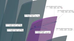
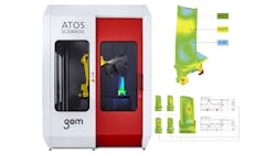
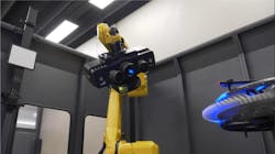
GOM’s blue light 3D scanners reduce inspection time from 18 hours using a CMM to about 45 minutes using an ATOS 5 with a Plus photogrammetry add-on configured with an ATOS ScanBox for automation (Figure 1). Capturing accurate measurements of unique areas of the blisk, such as throat area, leading and trailing edge radius, chord lengths, thickness, and bow and sweep with a CMM requires time-consuming point-to-point measurements and only produces results limited to the inspected areas. Previously the CMM used pre-defined, individual points and a technician programmed it to move the touch probe to contact the surface. With 3D scanning, the company consistently images entire parts by capturing a full field of data that provides a topographical map of the object’s surface and visualizes problematic areas, making it particularly effective for airfoil component inspection (Figure 2).
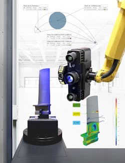
Errors that could be missed by a CMM include tolerance deviations from the design intent, trends in the tooling, and local dents and bulges as compared to smooth areas. High-resolution 3D measurement data and vivid color maps, however, reveal these errors. Having comprehensive part information allows the company’s research and development, quality, and production departments to quickly adapt to changing design requirements, which is why the company deploys blue light 3D scanners for quality inspection of blisks and other components including fan blades, compressor blades, turbine blades (Figure 3), and nozzle guide vanes.
For airfoil features requiring the use of a 3D scanner, the company achieves inspection times of about one hour for blisks and less than 20 minutes for fan blades, performing data acquisition in less than a fifth of a second. The company also achieved repeatability tests below five microns (0.005 mm), effectively speeding up blisk time-to-market.
The ATOS ScanBox includes an LR Mate 200ID industrial robot from Fanuc (Yoshino, Japan; www.fanuc.com), a sheet-metal safety enclosure, and an integrated rotation stage that provides an additional axis for robotic movement. The ATOS ScanBox is configured with an ATOS 5 3D scanner with a photogrammetry software add-on, reference frame, and accompanying ATOS Professional VMR (virtual measuring room) software.
Related: 3D laser profiler inspects cosmetics
Capture 3D provides a project template that includes a virtual measuring room containing the computer-aided design (CAD) model of the part with a digitized reference frame, and an inspection plan. The inspection plan includes the critical areas important to blisk performance, such as leading and trailing edge radius, various chord lengths, and geometric dimensioning and tolerancing (GD&T) requirements. The inspection plan contains these types of detailed information requests built from nominal geometries attached to the computer-aided design (CAD) model.
Using model-based definition (MBD), the required nominal geometries automatically import with the CAD model into the software. Then, the engineer applies a measuring principle to the nominal geometries to obtain values for the essential engineering specifications from the blisk blueprint. VMR software integrates with CAD, MBD, and product manufacturing information (PMI) data and includes these elements into the plan.
To begin the measurement process, the technician secures the blisk in a fixture, known as a reference frame, that goes around the part. The reference frame has reference point targets (RPTs) that increase the final accuracy without having to add targets directly onto the blisk. Often, blisks are a meter or more in size, and without a reference frame, technicians would need to manually place many of these adhesive targets on the large physical part. The reference frame keeps this use of targets as efficient as possible and results in the best possible measurement repeatability.
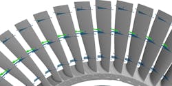
Next, the robot moves the 3D scanner, which collects blisk surface data from different orientations because each blade edge needs to be scanned at a specific orientation to collect the details needed on the sharp features. As part of the standard safety setup, everything inside the enclosure is modeled in the software, including the part in the fixture (Figure 4). VMR software saves time by automatically programming the robot movements using the CAD file instead of using more time consuming teach pendant methods or manually recording the robot positioning. The software communicates to the robot and rotation stage where to move to collect data all over the part, so the engineer does not have to spend time programming every position.
The VMR’s Smart Teach feature simulates the robot movements beforehand, automatically programming a path around the blisk and inserting any necessary positions to safely move around the part in optimal scanning positions. Finally, the technician activates the system, and the measurement begins. Due to the blisk's size, sharp edges, and intricate shape, accurately measuring and tracking the RPT constellation is essential to correctly transforming the data collected from each individual scan into a common coordinate system. Leveraging RPTs, the system tracks the quality of each measurement and monitors the setup’s stability, an important consideration because external factors such as temperature or system movement impact an RPT constellation’s constancy on a reference frame.
Related: 3D quality inspection robot cell speeds quality control testing
A photogrammetry software add-on accounts for changes by supplying an up-to-date constellation—or a photogrammetry session—before scanning, and during scanning, the use of RPTs allows the software to monitor potential changes that may occur during measurement. Each 3D scanning position includes a handful of the RPTs, which are compared to the constellation to know precisely where they belong. The result is a highly accurate 3D model of the blisk.
Upon scanning completion, another software capability automatically performs the analysis process with the project template. The ATOS Professional software automatically aligns the scan data with the CAD data and generates a full inspection report with dimensions, including those that are GD&T required. The software also uses its airfoil calculation functions to quickly analyze features specific to aerospace engineering such as edge point and edge circle creation, thickness, camber line, and throat area (Figure 5).

As part of the inspection report, the software generates color maps (Figure 6) representing deviations in the data and areas of concern where the blisk is in or out of tolerance. The aerospace company relies on these full-color maps to explain the results more quickly and clearly than trying to interpret spreadsheets and tables of data from a CMM, highlighting yet another advantage over the previously-used technology.
Joshua Old is an Application Engineering Manager at Capture 3D (Santa Ana, CA, USA: www.capture3d.com) and Ethan Senterfitt is an Application Engineer at Capture 3D.