Vision system measures dental morphology
In dental applications it is often necessary to measure the distances and angles between morphologically interesting points on dental crowns. Using orthometric systems, 3-D measurements are generally performed on plaster models, where the dental points are marked by small dots. To automate this process, Dr. Pertti Pirttiniemi and his colleagues in the department of dentistry and professors Janne Heikkilä and Olli Silvén in the department of electrical engineering at the University of Oulu (Oulu, Finland) have developed a vision-based system using an off-the-shelf video camera, a frame grabber, a PC, and special measurement software.
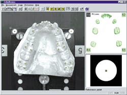
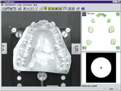
Based on a 400-MHz Pentium III CPU running Windows 95/NT 4.0, the vision system uses a SSC-C370P color CCD camera from Sony Electronics (Park Ridge, NJ) with a 12-mm lens mounted on a stand above the plaster model. The stand holds the camera in a fixed position and allows the plaster model to be turned in five different orientations. To digitize the images, the camera is interfaced to a DT3153 frame grabber from Data Translation (Marlboro, MA). The resulting images are displayed at 1024 x 768-pixel resolution on a Sony Multisync monitor.
During operation, five digital images of a plaster model are captured. The locations and the relationships of the measurement points are determined by picking them manually from the images. The amount of human intervention is minimized by a graphical user interface developed using Borland C++ language.
After the manual image measurements are completed, computation and camera calibration are performed with MatLab-based software modules converted to C++ using the MatLab compiler from The MathWorks (Natick, MA). These functions can then be called by the technician using the graphical user interface.
A crucial problem that confronted the system-design team involved camera calibration. "Modern CCD cameras are usually capable of a spatial accuracy greater than 1/50 of the pixel size. However, such accuracy is not easily attained due to various error sources that can affect the image formation process," Heikkilä says.
Whereas current calibration methods typically assume that the observations are unbiased and the camera model maps 3-D and image coordinates, this was not the case in this system design. Camera calibration turned out to be less accurate than expected. To overcome this drawback, Heikkilä developed a camera-calibration toolbox for MatLab that uses a bias-correction procedure for circular control points and a nonrecursive method for reversing the distortion model.
"Using this calibration method," says Dr. Pirttiniemi, "the accuracy of the resulting point locations in each dimension is better than 0.1 mm and can reach 0.01-mm accuracy; therefore, the 3-D structures, distances, and angles can be computed automatically."
After results are displayed, they can be saved as ASCII files that are accessible by other spreadsheet programs such as Microsoft Excel. For those interested in developing similar systems, the team has made the image-analysis and calibration software available from the University's Web site:www.ee.oulu.fi/~jth/orthometrics.

