Novel inspection system characterizes shiny reflective parts
Inspecting shiny, reflective parts for defects requires automated imaging systems employing novel illumination and imaging techniques
Parts such as automobile fittings and bathroom fixtures are often shiny and plated in chrome. To inspect these parts, manufacturers often employ manual operators to sample the consistency of the plating before they can be shipped to their customers for final assembly.
This manual processing is time-consuming and subject to human error. Due to the large number of parts produced, such manual inspection can often only be used to sample batches of product as they are produced.
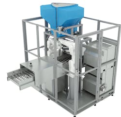
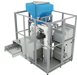
Figure 1: Helmee has developed its Covered Stereo Deflectometry (CSD) system specifically to automatically inspect the visual quality of high gloss surfaces of chrome-plated automotive parts.
To ensure that every part is inspected, Helmee (Tampere, Finland; www.helmee.com) has developed a novel automated inspection system that uses structured lighting techniques, industrial robots, and high-resolution cameras. In the design of the system, all the major components: robotics, lighting, cameras, software, and human-machine interfaces (HMI) play an integral role.
Related: Multiple 3D methods ease industrial automation applications
High-gloss parts are produced in various ways ranging from chrome-plating, physical vapor deposition (PVD), coating, and painting. These parts are usually decorative and it is understandable that OEMs require the surfaces of such parts to be free of blemishes. Items such as tap faucets, for example, must be shipped without any visible defects.
“Regardless of the production process, maximum defect sizes of 0.03 mm2 may be required to be detected. For human operators, discerning whether a defect is 0.03 mm2 instead of 0.04 mm2, and whether one or two more defects may occur every square centimeter is monotonous and difficult,” says Mika-Petteri Kuro, Sales Director at Helmee.
To address this problem, Helmee’s Covered Stereo Deflectometry (CSD) system has been developed to automatically inspect the visual quality of high-gloss surfaces of such parts. Chrome-plated automotive parts from Sarrel (Marolles-les-Braults, France; www.sarrel.com) and car key parts from HDO (Paderborn, Germany; http://hdo-gmbh.com) are currently being inspected using the system.
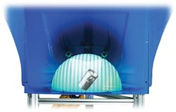
Figure 2: Using a six-axis robot, each part is picked from a tray and placed under a 180° reflective dome A light projector is then used to project a variety of sinusoidal patterns onto the object, thus creating a texture on the smooth surface.
Traditional methods
Traditionally, numerous different methods have been used to measure the surface of 3D parts. One of the simplest of these is to use passive stereo imaging methods in which the object is illuminated with ambient light and the surface imaged with a pair of calibrated stereo cameras. As the horizontal displacement of these cameras is such that the image captured by the two cameras overlaps, correspondence points can be found between the two and triangulation is used to determine the depth and surface profile of the object.
Related: Pivoting dual-lasers improve 3D bin picking
Such methods, however, have their drawbacks. If an object is highly specular, for example, there may be no—or very little—correspondence points that can be located between the two images. In such cases, depth, and thus the surface profile, cannot be calculated by capturing two stereo images. Such systems also suffer if parts contain multiple cavities or steep edges. In such applications, parts of the object may be seen by one camera but not another. Since parts of the image will be occluded, it is difficult to generate surface profile information across the complete part.
To somewhat overcome this problem, active-lighting systems can be employed. In the simplest of these–single structured-light projection–a light stripe is projected over an object as it moves down a conveyor belt. Alternatively, the light stripe is moved over the object. Reflected structured light from the object is then digitized by a calibrated camera to determine the line profiles across the object and build a 3D surface profile. Here again, light may not be reflected to the camera from objects with multiple cavities and multiple laser or laser/camera configurations may be required, thus adding to the expense of the system.
Figure 3: After the slope of the measured specular surfaces is calculated, the 3D shape of the specular surfaces can be reconstructed, and measurements taken to analyze any defects that may be present.
Phase measurement
Although both passive and active imaging systems can determine the surface characteristics of 3D objects, the problem of imaging highly-specular surfaces remains a difficult task, especially for parts with angular surfaces. To overcome this, a technique known as phase measuring deflectometry (PMD) can be employed.
Related: Dual camera system checks automotive electronic assemblies
In this method, a number of fringe patterns are projected onto the surface of the object to be inspected. In the Helmee system, these fringe patterns are generated by a STAR-07 pattern projector from Vialux Messtechnik + Bildverarbeitung (Chemnitz, Germany; www.vialux.de). To accomplish this, however, the part must first be placed under the illumination system.
Figure 4: Helmee CSD detects all surface defect types in chrome-plating and painting, including some of the most common defect types, pictured here.
Using a six-axis robot from FANUC (Rochester Hills, MI, USA; www.fanucamerica.com) each part is picked from a tray and placed under a 180° reflective semi-transparent hemispherical dome (Figure 2). The robotic system is programmed such that parts are picked to ensure that the surfaces to be inspected will be visible to the imaging system. Three STAR-07 projectors are then used to illuminate the part with several phase-shifted sinusoidal patterns, thus creating a texture on the smooth surface of the object.
Generated fringe patterns are then reflected from the part’s specular surface and appear deformed with regard to the slope variation of the measured surfaces and the modulated fringe pattern. In the CSD system, these images are then captured by three 4096 x 3000, CMOS-based ace acA4112 20 um USB 3.0 cameras from Basler (Ahrensburg, Germany; www.baslerweb.com). In this way, a complete profile of the surface of the part is illuminated and the reflected fringe patterns captured.
To calculate the slope of the surface of the object, the software developed by Helmee performs an automated analysis of the fringe patterns. Since the resultant images produce wrapped phase maps, these must first be removed in a process known as phase unwrapping to recover the surface shape. This phase unwrapping is used to obtain the absolute phase data that is then applied to calculate the slope of the measured specular surfaces (Figure 3).
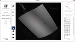
Figure 5: Defects are shown within the Helmee inspection software, which requires no programming skills for setup.
Using software developed by Helmee, parts such as bathroom fixtures (Figure 3, left) are then visualized to present the operator with both pseudo-colored vertical and horizontal surface gradients of the part and/or grey-scale versions of the vertical and horizontal gradients. This software can also display the scaled slope image of the part (Figure 3, middle).
To analyze the images, Helmee has incorporated functions such as basic filtering operations from both the Open Source Computer Vision Library (OpenCV; https://opencv.org) and proprietary software that is used to visualize any defects such as small pimples, scratches and dents that may be present (Figure 3, right). In this example, a small “pimple” defect approximately 0.03 mm2 is shown. For each part, any such defects are categorized as to type and number of defects.
Related: Vision system detects pharmaceutical contaminants
In this way, the system can store a complete record of the parts, part types, and defects as they are examined. By setting specific parameters using a graphical user interface, the operator can determine the level to which each part is acceptable. After the parts are inspected in this manner, good parts are then placed by the robot into a bin on the production line, while parts that have deemed to fail inspection are placed in a reject bin.
According to Matti Saarinen, CEO of Helmee, the system can inspect parts at the rate of 3-8 seconds depending on the complexity of the object. Currently, the company has numerous CSD systems in operation both in Europe and China. These are being used to inspect both complex automobile parts and bathroom fixtures. At a cost of between €350-450k per system, such systems both eliminate batch testing of products, eliminate human error and ensure that every part is inspected to the specific standards set by the manufacturer.
Companies mentioned:
Basler
Ahrensburg, Germany
Fanuc
Rochester Hills, MI, USA
HDO
Paderborn, Germany
Helmee
Tampere, Finland
Open Source Computer Vision Library (OpenCV)
Sarrel
Marolles-les-Braults, France


