Vision system ensures seal integrity
Stopper-measurement and defect-detection system delivers high speed using multiple cameras and lighting schemes.
By Lawrence J. Curran,Contributing Editor
Seal integrity is indispensable to guaranteeing the purity of vials of medical and pharmaceutical material, which is why an independent supplier of pharmaceutical packaging products is using a vision and lighting system to ensure that stoppers are defect-free before they are used. Since adopting the latest variation of this system 18 months ago, the company has substantially improved quality and cut labor costs. Using the system has also minimized scrap by rejecting only defective parts; the manual inspection used previously sometimes led to accidental rejection of the wrong parts or entire batches.
Ross Inspection Systems developed and installed six systems for this packaging customer. Previously, the stoppers were not inspected individually. Two inspectors, one each for a group of molding stations, performed a cursory check of the parts while they were on the compression-molded sheets on which they are formed.
The sheets hold more than 1000 parts, which are die-cut from the sheets, washed, and coated with silicone, which helps prevent sticking in bowl feeders. The bowl feeders move the parts into a starwheel that separates the parts so that they do not touch as they enter the imaging stations.
Because of the large size of the sheets and the time required for each inspector to supervise several molding stations, only grossly deformed parts were detected by inspectors. Entire sheets sometimes were scrapped when multiple defective parts were observed. The customer estimates that the cost of manual inspection was $45,000 per inspector, times two inspectors per shift, times the number of shifts.
This user graduated to automated inspection primarily to reduce costs, but also to cite improved quality in a highly competitive industry. The latest Ross system has been operating for about 18 months. The original two stopper-inspection systems have been in use for more than 3.5 years, and the first system installed for this customer has been working for more than 4.5 years.
Plug challenge
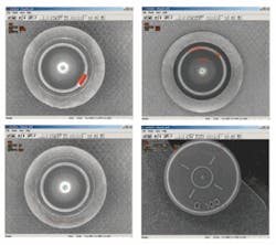
The parts are 20-mm-diameter, molded dark-gray rubber plugs for the pharmaceutical industry, which require high-precision measurement and inspection for multiple defects on both the top (head side) and bottom (cork side; see Fig. 1). Head inspection is performed while the part is held in a starwheel by a vacuum chuck, which supplies vacuum above the part to allow it to temporarily hang from the starwheel.
Once the parts are on the conveyor, they move to station 2, where a fiber-coupled optical part-in-place sensor initiates imaging, and an air jet blows defective parts into a scrap chute. Remaining parts are transported past stations 3 and 4, where similar sensors and air jets eliminate parts that are defective for other reasons. All parts remaining after station 4 are collected for shipment.
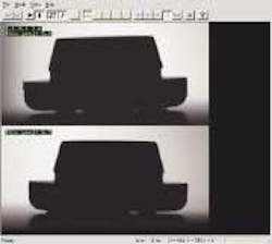
Measurements performed on the stoppers at station 4 include flange diameter, cork diameter, flange thickness, and relative centering of the cork on the flange. The precision required of all measurements is 0.001 in. Inspections done at stations 1-3 detect a variety of defects, including cork-rim blisters, cork-rim cuts, cork interior blisters, cork interior cuts, flange blisters, and flange holes and flange open knitlines.
The system catches defects as small as 1/256 in. at a production of 600 parts per minute on each of two production lines. With the requirement to inspect both sides of the part, and the need for two separate cameras for the cork side, the image-processing rate for a single defect PC is 1800 images per minute.
Inspection stations
Each conveyor requires three separate inspection stations (see Fig. 2). Each station consists of a progressive-scan, asynchronously reset, area-array camera, and a single strobed-LED light. For the two cork-side inspection stations, Ross uses 2-in. RL-201-W-RO LED ringlights from Metaphase Technologies, with each light having a different LED angle specification. A Metaphase model 101-W dual-ring off-axis ringlight is used for the head side. A single 1-GHz Pentium III-based industrial PC from Synnex processes images from all three inspection cameras on a conveyor.
FIGURE 2. Four stations inspect pharmaceutical vial stoppers with five cameras and custom-configured lighting. A duplicate configuration is installed on a second production line. Cameras 1-3 are progressive-scan, asynchronously reset, area-array models for defect detection. Camera 1 is illuminated by a dual-ring off-axis ringlight (A); cameras 2 and 3 use 2-in. strobed LED ringlights (B, C). The two cameras at station 4 provide measurement images of the stoppers illuminated by strobed white LED backlights (D, E).
The cameras for stations 1-3 are SenTech STC-1100A models from Sensor Technologies America. Station 4 uses two TM1320-24 models from JAI Pulnix, equipped with a Computar TEC-55 telecentric lens from CBC America. Images are collected by frame grabbers in the PCs. The SenTech camera (stations 1-3) are linked to a Coreco ITI IC-Asynch-4 board; the JAI Pulnix camera images are acquired by a Matrox Meteor 2-Dig/4/L unit.
The four system PCs are connected to the cameras, to each other, and to a local switch over a 10/100 BaseT Ethernet. The local switch has an additional port for a supervisory PC. An independent statistics application can be run on any or all of the inspection and measurement PCs, and/or on a supervisory PC.
Head inspection was complicated initially by the high-contrast appearance of the mold marks (target ring, radial lines and a cavity number). The cavity number is stamped into each part to indicate which mold-and which cavity of the mold-the part came from, so that the cause of defects can be localized, and the condition can be corrected.
Because the mold marks are normal, they must be located and ignored during processing. The target ring and the radial lines were reasonably consistent from part to part, and relatively easy to locate, but the cavity numbers were inconsistently located and grouped, making consistent location of them very difficult. The defects in the main and edge zones (cuts, blisters) had high contrast, and so they could be processed with relatively standard processing techniques. But defects in the target area could include a relatively low-contrast “roughness” defect, which, when combined with the shadow created by the target ring, required the use of a more sophisticated custom algorithm.
Cork-side inspection is done at two stations because of the multitude and diversity of the potential defects and the complicated shape of the product. Station 3 relies on a Metaphase white LED ringlight with a long focal range, which is good for detecting cuts near the bottom of the cork interior, shorts and cuts on the cork rim, and holes on the flange. Station 2 relies on another Metaphase white LED ringlight with a very short focal length. This design works well to detect cuts and foreign material on the sidewalls of the cork interior, blisters in the cork interior, and blisters on the cork rim.
Custom-configured lighting-not custom lighting-is one innovation to overcome the challenges this application presented. Standard lighting was used to control costs, but the structure of the light reaching the part was modified by varying the LED angles and focal point in the station 2 and 3 lights.
For both stations, the cork interior inspection was complicated by the large difference in gray scale between the bottom of the interior and the steep upper sidewalls. Rim inspection of the cork for dark defects (cuts and shorts) was complicated by acceptable roughness on the cork rim, which produced inconsistent background intensity. “Mottling,” caused by dirty molds and inconsistent silicone application, complicated flange inspection. To overcome these problems, Ross developed custom algorithms to detect defects without triggering too many false defects.
Measurement images were captured by the two JAI Pulnix side-viewing, high-resolution (1.3-Mpixel) cameras using the strobed Metaphase white LED backlights. Initial attempts to make measurements using an overhead camera were thwarted by inconsistent part shapes near the cork-to-flange boundary, which created variations in the reflections near the boundary, and made the critical cork-center-to-flange-center offset measurement inconsistent. Sideview imaging also provided a way to measure flange thickness, which permitted elimination of an aging and unreliable laser-based flange-measurement system. The biggest challenge this system presented was overcoming product variation. The primary sources of variation were shape variations caused by molds of significantly different ages, as well as surface-reflection variation caused by differences in the amount of silicone applied (see Fig. 3).
Other challenges included the complicated 3-D shape of the part, the need to inspect 100% of the surface, the large variety of potential defect types, the fast inspection rate for such a complicated application, the need to ignore several “normal” features of the part (mold marks and cavity numbers), and the need to do it all at an acceptable cost.
The lighting schemes, as well as the use of two imaging stations for the cork-side inspection, represent innovations to overcome these obstacles. The tendency is to minimize hardware costs, but hardware is steadily becoming more affordable. There were many different types of defects to detect on the cork side. Some were easier to detect with the longer-focal-length ringlight, others with the shorter-focal-length ringlight. Instead of using a compromise lighting design at a single station, Ross opted to include two cork-side inspection stations.
Having two optimal images instead of a single compromised image allowed lower engineering costs. It also led to a system that is better at detecting defects.features, advantages, benefits
“Our systems use COTS image-processing tools combined with custom functions developedin C/C++ or sometimes Assembler. We can usually reach 80%-90% of our objective using standard tools, but custom algorithms are a major part of the ‘magic’ embodied in our systems,” says Mike Leary, engineering manager at Ross Inspection Systems, which led the development of the pharmaceutical-seal inspection system.
An example of the use of custom algorithms is in isolating the extremely variable mold-cavity numbers into a defect-detection exclusion zone. “We used parallel, multiple edge-detection and contrast-analysis techniques to detect potential cavity numbers, thencombined the results of the detection function into a consensus ‘vote’ of whether the detected regions were cavity numbers or actual defects. Even if the rest of the system worked perfectly, the system would have been of no use if it triggered false rejects and/or missed too many defects,” says Leary.
Company Info
CBC America, Commack, NY, USAwww.cbcamerica.com
Coreco Imaging, St.-Laurent, QC, Canadawww.imaging.com
JAI Pulnix, Sunnyvale, CA, USAwww.jaipulnix.com
Matrox Imaging, Dorval, QC, Canadawww.matrox.com/imaging
Metaphase Technologies, Bensalem, PA, USAwww.metaphase-tech.com
Ross Inspection Systems, Nanuet, NY, USAwww.rossinspection.com
Sensor Technologies America, Carrollton, TX, USAwww.sentechamerica.com
Synnex, Fremont, CA, USAwww.synnex.com


