Understanding unique machine vision illumination methods
By Jeremy Govier and Cory Boone
Proper illumination is critical to the success of machine vision applications. Different use cases call for vastly different illumination types to maximize performance. This article covers the advantages, disadvantages, and use cases for several unique machine vision illumination methods such as in-line, telecentric, and diffuse axial illumination.
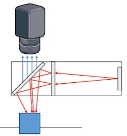
In-line, or coaxial, illumination (Figure 1) incorporates a light source, such as a fiber optic light guide or LED source, directly into the optical train of an imaging lens system, often using a beamsplitter. This is a type of bright-field illumination, meaning that specular reflections will come back into the lens because the reflections’ angle of incidence is smaller than the field of view of the lens. Like other bright-field illumination techniques, in-line illumination results in images with a bright object against a dark background.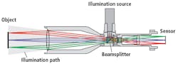
In-line illumination typically results in more compact vision systems than those using other types of illumination such as diffuse axial illumination. Ideally, the light source used for in-line illumination (Figure 2) should be large enough to be considered diffuse, as this prevents the source itself from being imaged back into the imaging system off specular parts of the object.
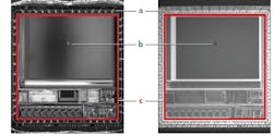
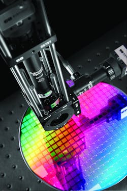
The ray path of in-line illumination makes it well-suited for the inspection of specular or semi-specular objects such as semiconductors or CCD sensors. Figure 3 compares an image of a CCD sensor captured using in-line illumination compared to an image of the same CCD sensor captured using dark-field illumination. While in-line illumination offers even illumination with consistent contrast between fine features for specular objects, its main disadvantages are stray light and low contrast. Some portion of light will bounce off the surfaces of the beamsplitter and back into the camera without reaching the object, resulting in a general “washing out” of the image. This may also cause a hot spot in the center of the image, as most of the stray light will land on the middle of the camera’s sensor.
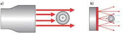
Telecentric illumination is a special case of backlighting in which the light source is collimated, not diffuse. The light rays coming from any field point of the illuminator will be parallel to all other illumination rays (Figure 4). Instead of reflecting off specular objects back into the imaging lens, telecentric illuminators are separate modules consisting of a telecentric lens assembly and an LED source that backlights objects.
Collimated rays leaving the illuminator silhouette the object without striking the surfaces facing the imaging system, while conventional backlight illuminators have rays coming in from sharp angles that strike the front of the object and scatter back into the imaging lens. This causes edge features to brighten and lose contrast in conventional backlighting (Figure 5).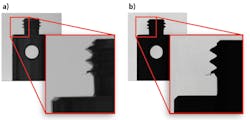
The main benefit of telecentric illuminators is their high level of collimation, which increases edge contrast and makes them ideal for accurate measurement and gauging applications. These high-contrast silhouettes allow for superior identification and measurement of small defects, increased measurement repeatability and accuracy, and the ability to decrease the distance between the illuminator and the object. Conventional backlighting requires more distance between the illuminator and object to reduce scatter from rays at steep angles.
Telecentric illuminators also offer high uniformity. However, telecentric illuminators are often larger and more expensive than other illumination options available on the market. The size of the front lens element determines the diameter of the illuminated spot, leading to a larger system size and weight. Telecentric illuminators are also sensitive to the alignment between the lens and light source.
In diffuse axial illumination, the lens looks through a beamsplitter which introduces light from an external diffuse source into the optical path towards the object (Figure 6). The illumination and lens are coaxial after the beamsplitter, similar to in-line illumination. However, diffuse axial illumination projects light onto the object at a multitude of different angles in a combination of both bright-field and dark-field illumination methods.
Diffuse axial illumination results in very even and diffuse illumination, reducing glare and the bright spots caused by both specular and diffuse objects. However, diffuse axial illumination tends to be larger and more difficult to mount than in-line illumination. It also has a limited working distance range, and relatively low throughput. Multiple fiber optic light sources may be required to provide proper illumination. Like in-line illumination, the large area of the source causes any specular reflections to reflect a large enough image of the light source back to the camera that no single hot spot is formed. The specular object will be evenly illuminated.
No single illumination method is the optimal choice for all situations. The object being imaged and goals of the inspection impact the effectiveness of different illumination techniques, making the choice of illumination highly application-dependent. Highly accurate measurement of the silhouettes of objects benefits from telecentric illumination, while space constrained inspection of specular objects such as semiconductor wafers will benefit more from in-line or diffuse axial illumination. Understanding the different types of available illumination will ensure that you choose the proper illumination method to maximize the performance of your system.
Jeremy Govier is the Principal Engineer, Imaging Business Unit, and Cory Boone is the Lead Technical Marketing Engineer at Edmund Optics (Barrington, NJ, USA; www.edmundoptics.com)
Related stories:
Machine vision lighting companies address niche imaging requirements
Fourier-transform analysis helps optical method improve RA detection
Polarization in imaging: Things you did and didn’t know it could do
Share your vision-related news by contacting Dennis Scimeca, Associate Editor, Vision Systems Design
SUBSCRIBE TO OUR NEWSLETTERS