Lens choice makes the difference
Choosing the correct machine-vision lens requires an understanding of lens parameters and the application.
By David M. Berg
With the advent of low-cost personal computers and their increase in performance, developers began to produce machine-vision systems for the manufacturing market. Lenses for these early systems were chosen from the fields of security cameras and 35-mm photography.
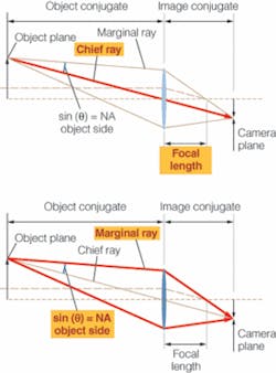
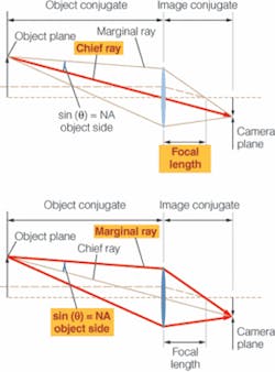
Today, machine vision is a widespread technology. Numerous vendors offer lenses developed especially for vision applications. Choosing a lens involves understanding a long list of lens parameters that include the focal length, field of view (FOV), sensor format, f-number, depth of field (DOF), and minimum focus distance. While, at first, this list may appear overwhelming, it can be simplified into four general categories: the chief ray parameters, marginal ray parameters, interface, and cost parameters (see Fig. 1).
Parameters determined by the chief ray include FOV, focal length, distortion, and the telecentricity of the lens. Parameters determined by the marginal ray include the f-number, DOF, and the resolution. Interface parameters, including size, weight, mount type, and minimum focus, describe the way the lens fits in the physical world. Knowing which requirements drive the cost of the lens permits the developer to make the most cost-effective choice. By classifying lens parameters in this way, deciding which lens is better for any specific application becomes easier.
Lens choices
A number of lens types exist for both general and specialty applications. Standard vision lenses, large-format and linescan lenses, microscope, and enlarger lenses are common in general machine-vision and industrial inspection applications. For more specialized applications, long-working-distance, telecentric, anamorphic, and multiple-view lenses are available in both off-the-shelf and custom versions.
Many machine-vision lenses are optimized for 0.1-1X magnification, 2/3-in. standard sensor formats. Large-format (40-90-mm diagonal) linescan lenses specifically for machine vision are becoming available. Many vendors offer lines of telecentric lenses used for precision gauging and alignment applications.
Anamorphic lenses also can meet the needs of certain applications. Unlike telecentric lenses, they must be custom designed and built for each application. Similarly, by incorporating mirrors and prisms into lenses, multiple views of objects can be formed on a single sensor. These techniques can improve system stability and save both cost and space in a machine-vision system.
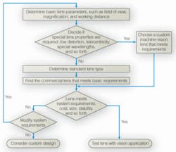
A flow chart provides assistance in choosing a lens (see Fig. 2). After deciding on the first-order optical properties, including FOV, magnification, and working distance, the developer must decide whether any special properties such as low distortion and telecentricity are required. If a commercial lens meets the system requirements in terms of cost, size, and weight, it can be tested in the application. If not, a custom lens may be required.
case studies
Four case studies highlight the varied design choices available to developers of machine-vision systems. The first is a system designed to inspect the interior of the rim of battery cans for defects. The batteries are manufactured at high speed, and the important defects, when they occur, are large. High-resolution images are not required.
Because of the small space available on the production line, the relatively large size of the defects, and the cost-sensitive nature of the application, it was initially determined that a single camera with a fish-eye lens could image the complete rim of the battery can sufficiently. However, since the camera needed to be mounted far above the battery can for production-line clearance, this approach was abandoned in favor of a system that captures multiple views with a single lens/camera system.
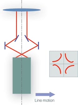
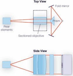
The solution consists of a single telecentric lens and two “fold mirrors” to direct oblique views of the can into a vertical lens (see Fig. 3). Since each slice of the image includes an area greater than 90°, the complete circumference of the rim is imaged. The successful design of the system depends upon balancing a number of design constraints, only some of which are optical.
Cigarette inspection presents several different challenges. Many cigarettes are manufactured as double-cigarettes joined at the filter end. Although the cost of each cigarette is relatively low, the cost of dealing with defects is high. A production machine manufactures tens of thousands of cigarettes per day. Therefore adding machine vision for every part inspection is cost-effective. The vision system must inspect the whole circumference, gauge defects along the entire length, and integrate seamlessly into the production process.
Because the cigarette is held along its length on one side, it takes two stations to inspect the whole circumference. Since each station must inspect 180°, at least two views are required. To properly gauge the defects along their entire length requires a telecentric lens. However, because any standard 200-mm-diameter telecentric lens is large and expensive, an alternative approach was sought.
A single lens and camera at each station was required to reduce space and cost. Like the battery-can inspection system, these constraints impose restrictions on the optical design. And, like the battery-can inspection system, the final unit consists of a custom-built telecentric lens with a fold mirror and reflective prism to direct an oblique view of the object into the lens (see Fig. 4). In this way, a single-lens, single-camera solution meets the requirements of the cigarette manufacturer.
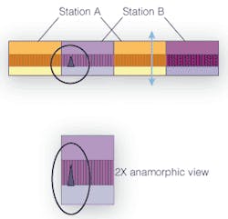
Using custom optics can improve the performance of machine-vision systems in other applications. Like cigarettes, disposable cutting blades are manufactured in very high volume at high speed. While this application is less cost-sensitive, the installed machine-vision system must take up as little space as possible on the production line. It is extremely important to ensure that there are no defects across the cutting edge of the blade. Only the edge of the blade needs to be imaged at high resolution. By matching the resolution of the image to this requirement, anamorphic lenses reduce the number of lens per camera units required.
Anamorphic lenses capture a wider perspective across the field of view of the y-axis. In the film industry, anamorphic lenses provide cinematographers with the ability to capture wider fields of view on standard 35-mm film. When such images are reconstructed at theaters, the effect produces “wide-screen” images. Likewise, these lenses can capture wide images in machine-vision applications.
In this application, each production line uses four anamorphic lenses: two lens/camera units at each of two different inspection stations (see Fig. 5). The resolution of the collected image is twice as great across the blade as along it. Using traditional lenses, eight cameras would be required. Collecting high resolution only across the edge also reduces the processing bandwidth, making use of every collected pixel
Developers of machine-vision systems also must be aware that advances in components such as lighting and software affect their designs. One challenge recently faced by Machine Vision Direct, for example, was the inspection of beer barrels for gas leaks (see Vision Systems Design, July 2006, p. 31). This high-speed, on-line application was initially studied some ten years ago. At that time, the available pattern-matching software was extremely sensitve to magnification. Because of this, a telecentric lens was required to image the top of the beer barrel. With the advent of geometric pattern-matching software, it is no longer necessary to capture every image with the same magnification. Consequently, standard off-the-shelf lenses can be used, resulting in reduced system cost.
DAVID M. BERG is principal, Oren Sage Technology, Rochester, NY, USA; www.orensage.com.
null
