On the Road Again

Liviu Bursanescu, Marc Lemay, and Mihaela Bursanescu
Road and highway administrators are confronted with an increasing need for information regarding the status of existing infrastructure—from pavement shape and status to walkways, guard rails, rumble strips, pavement markings, signs, poles, and bridges. Even though some types of data collection are subject to standards or to already accepted rules, most data are gathered according to the specific application. Therefore, a versatile image collection system is needed.
To meet the needs of road infrastructure managers, GIE Technologies has designed the Image Capture System, a vision system based on high-resolution (1600 × 1200 pixels) cameras that provides a user-friendly approach to installation and use. The design has three main objectives: high-resolution; high-quality images at highway speed by controlling exposure value and shutter, precise positioning, and various triggering intervals through independent triggering channels; and various image formats at the same high resolution.
The camera interface chosen for the system is IEEE 1394a (FireWire) with a bandwidth of 400 Mbits/s. This ensures high-speed images transfer to computer via an IEEE 1394 adapter without using a frame grabber. The system supports up to three color or monochrome cameras.
Color cameras from Point Grey Research use the Bayer CFA (color filter array) pattern, thus allowing monochrome image transfer to a computer without sacrificing speed. Color rendering is made in postprocessing along with image extraction. Large files allow the operating system to keep up the speed. Programmable lower resolutions (1280 × 980, 1024 × 768, and 800 × 600 pixels) are available for higher-speed or custom applications. These options were added also to fit a variety of image formats already present in existing databases. The cameras comply with the IIDC 1394-based Digital Camera (DCAM) Specification Version v1.30 and the IIDC 1394-based Digital Camera Specification Version v1.31 for extended functionality, video formats, and frame rates.
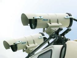
The cameras are protected from rain and dust in special Pelco enclosures with a sun shroud and a dual-element heater/defroster. When the temperature drops below 2°C (70°F), the first element turns on for defogging. The second element turns on for defrosting when the temperature falls below 4°C (40°F) (see Fig. 1).
System design
Inside the enclosures, cameras use motorized lenses from CBC Corp. that allow remote control by software of zoom, focus, and iris. The cameras’ field of view and depth of field can be adjusted by modifying the focal length in the 8- to 48-mm range.
Lenses are provided with special antiglare polarization filters that prevent reflected light from reaching the cameras. This type of filter ensures the same image quality regardless of the presence of potential reflecting surfaces such as windows, vehicles, water surfaces, and ice. The efficiency of these filters was tested on reflecting surfaces such as water and car windows.
Software control over the motorized lenses is achieved via a two-channel lens controller provided from Image Labs International that is plugged into a serial port of the computer. A calibrating routine can be performed on the zoom and focus channels, thus allowing establishment of known settings as well as saving of preset values. Without calibration, lens motors are activated in steps of preprogrammed duration (for example, 5000 ms). The third camera uses a manual lens but it can also be configured with a motorized lens and a single-channel lens controller (see Fig. 2).
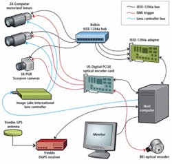
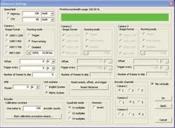
Each camera can be hardware triggered by a dedicated channel of the Distance Measuring Instrument (DMI). This approach avoids any software latencies that can occur with a software trigger and allows a precise triggering interval. The DMI is based on an optical encoder card from US Digital and an optical encoder from BEI Technologies.
Each DMI channel can be programmed with its own settings, so each camera can have its own offset with respect to its position on the vehicle and its own triggering interval. A global preset is available if the desired starting point is not the origin of distance measurements. The DMI is compatible with any TTL quadrature optical encoder and can be set in both English and metric units. The system also can capture and integrate global-positioning-system (GPS) data via a serial port. It was intensively tested with the MS750 receiver from Trimble.
In addition to the internal 80-Mbyte IDE hard drive, high storage capacity is provided by two 200-Gbyte removable SATA Western Digital hard drives. A fourth fixed IDE drive can be added as an option.
Image-capture software
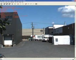
The software for the image-capture system includes all needed features to control all hardware, automatically adjust camera settings, choose the image-capture mode, and designate the storage devices and files sizes. It includes DMI and trigger configuration, lens control, and GPS capture, as well as the integrated postprocessing software for image extraction, embedded timestamp retrieval, color rendering, and image export (see Fig. 3).
The application was developed in C++ for the Windows XP operating system. For this development Microsoft Visual Studio 2005 from Microsoft was used, and the API was provided by Point Grey Research.
Three operating modes are available: the free running mode, when the camera operates at the highest available frame rate; trigger mode, when each camera is triggered by the DMI at a preprogrammed interval; and skip-frames mode, when the camera will skip to transmit a preselected N number of frames from each N+1 frames grabbed (see Fig. 4).
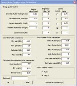
The configuration routines allow automatic setting of exposure, shutter, and gain values for each camera. High shutter speeds are used to limit blur from vehicle movement. Four discrete shutter configurations are available: 0.25 ms (bright sun), 0.5 ms (sunny), 1 ms (cloudy), and 2 ms (low light). The continuous shutter configuration, provides the best balance over gain and shutter, aiming for the lowest possible shutter value. The type of configuration depends upon the environmental lighting conditions. A dialog box can be accessed to fine-tune settings (see Fig. 5).
Once the configuration routine is chosen, the camera will auto-adjust its gain to keep the exposure value that was set without modifying its shutter value. Image capture and storage are made possible only after setting configurations were performed on each active camera; then image capture can be done individually or simultaneously on the same bus. The operator can start simultaneous image capture for all active cameras or choose to separately start each image-capture process according to the application.
The postprocessing routines extract images from large files, extract frame-specific information from the first four pixels of each image, process color images to render color, and export images in one of the supported file formats (RAW, BMP, JPG, TIFF). Time stamps, DMI positions, and GPS coordinates are combined in a positioning file indexed with images’ sequential numbers.
Liviu Bursanescu is vice president of research and development and Mihaela Bursanescu and Marc Lemay are staff researchers at GIE Technologies, Montreal, QC, Canada.
features, advantages, benefits
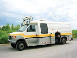
The complete Image Capture System is delivered to the customer ready to run. It can be custom configured according to specific needs and can be installed on any vehicle. Standard configuration includes two color cameras and one monochrome camera. Any combination of color and monochrome cameras can be provided.
The system was successfully tested in many configurations at highway speeds. In one test, two cameras were triggered every 5 m, and the third was triggered every 10 m. Fill images (1600 × 1200 pixels) were acquired with all cameras. At 90 km/h the images were still clear with no noticeable blur, and all images were stored without any loss of frames.
Company Info
BEI Technologies, Goleta, CA, USA
www.beiied.com
CBC Corp., Commack, NY, USA
www.computarganz.com
Edmund Optics, Barrington, NJ, USA
www.edmundoptics.com
GIE Technologies
Montreal, QC, Canada
www.gieinc.ca
Image Labs International
Bozeman, MT, USA
www.imagelabs.com
Pelco, Clovis, CA, USA
www.pelc.com
Point Grey Research
Richmond, BC, Canada
www.ptgrey.com
Trimble, Sunnyvale, CA, USA
www.trimble.com
US Digital, Vancouver, WA, USA
www.usdigital.com
Western Digital
Lake Forest, CA, USA
www.westerndigital.com
null