Vehicle-mounted imaging system Measures road Conditions
Vehicle-mounted imaging system Measures road Conditions
By Sandra Todd and Liviu Bursanescu
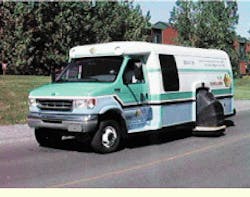
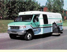
A mobile (truck-mounted) imaging system, the GIE Technologies (Montreal, Quebec, Canada) LaserVision System (LVS), uses laser-based technology to obtain accurate quantitative data in real time and at high speeds concerning the conditions of road and highway surfaces. The LVS integrates three-dimensional (3-D) laser-sensing imaging with a global positioning system (GPS) to map the cracks, ruts, roughness, and repair patches in paved road surfaces at monitoring speeds up to 72 km/h.
The LVS simultaneously records a three-dimensional (3-D) surface map along with photometric data using the same set of Biris (bi-iris) sensors. These sensors were developed for this application by engineers at GIE Technologies Inc. under exclusive license from the National Research Council (Ottawa, Canada). They rely on a combination of defocusing and trigonometry principles to record 3-D contour information about a test surface (see "How the laser vision system works," p. 30).
Laser vision
The Biris approach for a mobile pavement-testing system offers several performance advantages in comparison to other sensing methods (see Vision Systems Design, Nov. 1997, p. 18). Most important, a Biris sensor uses all-solid-state components with no moving parts. This rugged design is highly resistant to misalignment and performs well in a moving (continuously vibrating) vehicle (see Fig. 1). Moreover, range and intensity information are simultaneously recorded and registered. The photometric (intensity) information provides complementary data where ranging alone proves insufficient, as when detecting sealed road cracks or patches. In addition, the range analysis uses simple trigonometry to obtain real-time performance. For analysis, the derived results mean that large amounts of data can be recorded and stored as road-surface information, instead of as raw data that would have to be subsequently processed and analyzed.
In developing this mobile imaging system using Biris sensors, the three main design considerations were measurement speed, resolution, and signal-to-noise ratio (S/N). A preliminary analysis showed that road sampling every 11 cm in the direction of travel and continuous in the wheel paths would result in accurate measurements of all the key road surface parameters.
However, a system requirement mandated the use of standard 60-Hz (RS-170) video processing of the charge-coupled-device (CCD) output for cost and simplicity and to allow vehicle speeds as high as 70 km/h. This restriction dictated the use of six CCD cameras from Panasonic (Secaucus, NJ) with three line projectors per camera to triple their coverage. Each camera is also equipped with a 15-nm full width half maximum (FWHM) bandpass filter to discriminate against background light and a high-speed shutter to eliminate profile overlap and excessive blurring.
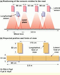
Consequently, to cover a standard highway lane width of 3.6 m, the system uses four sensors to generate 1024 measuring points, resulting in a 3.5-mm lateral resolution (see Fig. 2). The separation of the three laser lines is a nominal 11 m; therefore, 33 cm of the road is monitored per sampling frame. At a 60-Hz frame rate, the truck-mounted LVS can be driven at speeds up to 20 m/s (72 km/h) before gaps occur in the data. At speeds slower than 72 km/h, the vehicle is monitored by the host system controller, which automatically removes data redundancy.
The two longitudinal sensors are mounted closer to the road surface because their field-of-view distance must be 33 cm for continuous wheel-path measurements. In fact, the distance of 50 cm was chosen, as this span delivered an effective resolution of <3 mm. These two sensors are used for transverse detection and longitudinal surface profiling. The range resolution is better than 0.1 mm for all six sensors.
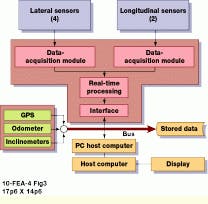
The complete LVS also includes distance- and position-measuring equipment, inclinometers, and a PC-based data-processing/analysis system (see Fig. 3). The distance traveled is recorded using an optical encoder from Data Technology Inc. (Wilmington, MA) that is mounted on the vehicle`s drive shaft. Geographic coordinates are determined using a GPS receiver. The GPS receiver, central computer, and data-acquisition boards are supplied by Industrial Computer Source (San Diego, CA).
Due to the large amounts of data generated, real-time digital-signal processing is performed on the raw data using a 1.6-Mbyte/s parallel processing system from Alta Technology (Sandy, UT). The range data are complemented with information for vehicle inclination in real time using signals from inclinometers produced by Jewell Electrical Instruments (Manchester, NH). In addition to the road-surface sensors, the truck-mounted LVS also acquires a video record of the road. The positioning information is transferred on the acquired images by a character generator board supplied by Chyron Corp. (Melville, NY).
System software, developed by GIE Technologies, allows the LVS to derive results such as a log of different categories of road defects and the material and costing estimates for complete road repair.
Computer system
The LVS computer system consists of a single-board computer--a 200-MHz/32-Mbyte RAM Pentium PC mounted in an industrial-grade chassis--from Industrial Computer Source. The PC serves as the host processor and controls all the integrated data-acquisition technologies located on board the surveying vehicle. These technologies include 3-D ranging for the surface distress survey, inclinometers for grade and crossfall measurements, a global positioning system for geographic coordinates, and a distance measuring instrument for linear positioning. The 3-D ranging technology is operated by a transputer array of 29 T805 SGS Thompson processors. These processors perform the data-acquisition functions for the six Biris sensors and the real-time processing of the acquired data.
The real-time processing deals with four main functions: it corrects the acquired profiles` positions, sews the profiles together for complete transverse and longitudinal profiles, filters the profiles and detects events, and stores all the events. Real-time processing also computes the profiles for the rutting measurements. With these procedures the amount of stored data is optimized so that a smooth surface doesn`t produce data to be stored. The data-acquisition software is integrated in a user-friendly Visual Basic graphic interface. All set-up and data-acquisition functions are accessible with a mouse click.
The postprocessing of data is performed with GIE`s DistressView software. The preprocessed data are analyzed and classified starting from the stored events and the rutting profiles. The software is loaded into the Pentium PC`s 6- to 8-Gbyte storage capacity to accommodate the data.
Events are put together and analyzed by statistical algorithms. The system output produces project/network-level reports about user-specified road sections. The reports are based on the IRI (International Roughness Index) in both wheel paths, rut depth, and cracking. Output data can be exported to most existing database formats. The system can also provide, upon request, 3-D images of rutting, the cracking pattern on selected road sections, and user-specified cross sections.
These images are retrieved by the system from individual transverse profiles pasted together (one profile for every 4 in.). The DistressView software is developed for the Windows 95 operating system. The display of 3-D images requires a computer monitor with a minimum resolution of 800 ¥ 600 pixels and a color depth of 16 bits. The system is currently using a 17-in. monitor from NEC Technologies (Santa Clara, CA). Data can be processed either on the on-board computer or transferred to another PC with similar features.
Line projector
During the development of the prototype LVS, data quality was limited by the output power and the beam uniformity of the line projectors. In the production LVS, these problems were eliminated by using novel lasers and optics.
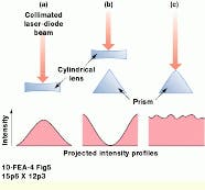
The common method of transforming a laser beam into a line, without scanning optics, is to use a cylindrical lens. Unfortunately, this approach does not generate a line of uniform intensity (see Fig. 4). Rather, it produces a stretched version of the pseudo-Gaussian intensity profile of the laser. While some nonuniformity can be compensated for during system calibration, this profile limits the effective dynamic range of the CCD.
This problem was solved by installing integrated projector subassemblies in the LVS from Lasiris Inc. (St. Laurent, Quebec, Canada). These projectors use the company`s passive uniform line-generation system. For laser operation, a prism with a rounded edge is used. The center of the input beam is transformed by a surface that acts like a cylinder lens, whereas the edges of the beam are transformed by the planar sides of the prism. By carefully matching the radius of the prism edge to the input beam diameter, this method produces a line with intensity variations as small as 䔳%.
Laser-diode advances
Until recently, several performance problems have constrained the use of high-power laser diodes. For example, at near-infrared wavelengths (750 to 850 nm), the practical output power of a single laser diode, with a commercially viable lifetime, was restricted to less than 1 W; even lower powers were available for visible (630- to 670-nm) laser diodes. Higher powers can be achieved by using a large active junction, which limits the ability to focus the laser beam, or by operating at higher drive currents, which reduces operating lifetimes in a nonlinear fashion. Indeed, the major performance trade-off for laser diodes has been power versus lifetime. Devices with output powers of >500 mW typically have offered operating lifetimes of a few thousand hours at best.
In response to this situation, engineers at the Coherent Inc. laser-diode fabrication facility in Santa Clara, CA, have succeeded in increasing the ratio of output power to active junction area, thereby improving the device focusability (brightness) without sacrificing lifetime. This improvement has been made possible in part by the development of a new semiconductor-laser material.
Historically, short-wavelength laser diodes have been made of AlGaAs (gallium arsenide doped with aluminum). With this material, shorter wavelengths, such as 800 nm, could be achieved only with a large aluminum content. However, over time, the aluminum reacts with oxygen in the air, and this oxidation contributes to limited device performance.
By using an aluminum-free material, which contains phosphorous and indium instead of aluminum, the Coherent engineering team has developed laser-diode devices that avoid this oxidation problem for wavelengths of 780 nm. In addition, the team has developed high-volume fabrication methods using a molecular-beam-epitaxy (MBE) process instead of the traditional metal-oxide chemical-vapor-deposition process. The MBE method produces laser diodes that are more consistent in performance than earlier lasers and shows superior far-field beam uniformity. As a result, for the LVS application, the laser diodes operate at 810 nm, generate output power up to 2 W, and operate with lifetimes exceeding 10,000 hours.
System performance
The LVS prototype was developed before the latest laser diodes were available. Each of the system line generators, therefore, used a 790-nm diode with an output power of just 90 mW. At this power, the CCD shutter had to be open for 2 ms to obtain data with acceptable S/N. These parameters limited the maximum travel speed of the LVS. At the high-travel speed of 72 km/h, the system produced imaging blur that was an unacceptable 40 mm in the object plane (road surface).
In the improved LVS, the Lasiris line projectors use Coherent long-life 810-nm lasers with output powers of 2 W each--a 20X increase. This power level provides adequate S/N with shutter speeds as short as 0.1 ms, resulting in only 2 mm of blur at 72 km/h.
Rating the absolute performance of the automated LVS in terms of feature detection is complicated by the lack of an objective reference standard. For example, when using manual road-surveying techniques, experts differ by as much as 15% in their assessments of overall surface distress for a given road section. Based on tests on several well-calibrated sections of road, the LVS showed test correlation factors of 97% over standard methods (see Fig. 5). It has been adopted by several government agencies, including the Quebec Ministry of Transportation in Canada and the New York State Department of Transportation in the United States.
How the LaserVision System works
The Biris-sensor approach to road-surface mapping uses a laser to produce a spot on the test surface (see figure). This spot is imaged onto a detector array using an imaging lens and a Biris mask. Placed in front of the imaging lens, the mask contains two small irises or holes that are equidistant from the system optical axis. Because the lens focuses the image beyond the plane of the detector, each of these two holes produces a separate spot on the CCD detector plane.
The separation of these two spots in the CCD plane is a function of the object range, or¥distance, while the geometrical center yields the x and y coordinates. This separation is determined by how far the system is out of focus, which, in turn, is a function of the distance between the lens and the test surface. The separation of the image spots can therefore be used to determine the distance to the test surface. To map an extended road surface using the LaserVision system (LVS; GIE Technologies; Quebec, Canada), the laser projection optics are set up to produce a line instead of a spot that is perpendicular to the line connecting the two holes in the mask.
To measure entire surfaces, as in pavement monitoring, a laser line projector is used instead of a single spot. This line is perpendicular to the axis connecting the two holes in the Biris mask, so that two image lines are formed at the CCD. The separation of these lines thus provides depth (z) information across their entire length. By translating the sensor/line projector assembly, extended surfaces can be profiled.
S. T. and L. B.
SANDRA TODD is director of marketing at Coherent Inc., Semiconductor Group, Santa Clara, CA, and LIVIU BURSANESCU is vice president of research and development at GIE Technologies, Montreal, Quebec, Canada.
A laser-based truck-mounted imaging system from GIE Technologies can simultaneously measure all aspects of road surface distress, such as ruts, cracks, and surface roughness, at travel speeds of up to 72 km/h.
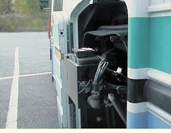
FIGURE 1. The GIE Technologies Inc. LaserVision System uses six, three-dimensional (3-D) laser sensors to acquire road surface distress data--four lateral transversal sensors and two longitudinal sensors. Two transversal sensors are mounted in working positions on each side of the data-collection vehicle. Four sensors--two transversal and two longitudinal--are positioned inside the vehicle and sample the road surface through special openings in the vehicle`s floor. The data collection geometry allows the inspection of a 6-, 9-, or 12-ft-wide lane.
FIGURE 2. The LaserVision System uses six sensors, each viewing three projected laser lines (a). Each of the four transversal sensors samples the road surface perpendicularly to the ride direction over a 90-cm width. The LVS can thus make transversal measurements on lane widths up to 3.6 m. The longitudinal field of view of the transversal sensors is 33 cm, which allows the test vehicle to be driven at up to 72 km/h with no data gaps (b). The two longitudinal sensors make longitudinal measurements on the wheel lanes, which are 170 cm apart. Each measurement covers a 50-cm length of the wheel lane.
FIGURE 3. Road surface data are acquired through the four transversal Biris sensors and the two longitudinal Biris sensors. A fast 1.3-Mbyte/s real-time parallel-processing unit converts raw intensity data to road-surface dimensional data. The system personal computer (PC) builds up a road surface map by combining the road surface data with information derived from the three positional sensors--a GPS device, an odometer, and a set of inclinometers. Information from the inclinometers allows the system software to correct the road surface data for changes in attitude of the vehicle as it travels along the road and compute the geometrical characteristics of the road (gradient and crossfall).
FIGURE 4. The simplest laser line projector uses a cylindrical lens (a). But the projected line retains the original beam intensity profile, which is typically Gaussian. Alternatively, a prism may be incorporated to reverse this profile so that the intensity maximum is at the edge of the line instead of at the center (b). The passive uniform line generator from Lasiris uses a novel-shaped optic that contains both cylindrical and prism surfaces to generate a line with intensity variations as small as 15% (c).
