SPOTLIGHT - Detecting Defects in Dinnerware
Dan Milkie
No manufacturing process is perfect, and the production of earthenware dinner plates is no exception. Plates may not meet the dimensional tolerances that are demanded by the manufacturer, and even if they do, defects can potentially arise on the surface of the plates themselves, including small bumps that may be formed in the glaze during the firing process.
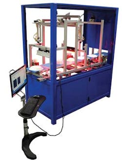
Traditionally, inspecting dinnerware has been an expensive, manually intensive process in which trained personnel individually examine each dish for potential defects. But now, thanks to a vision-based Plate Quality Inspection System (PQIS) developed by Coleman Technologies for a large dinnerware manufacturer, the entire inspection process has been fully automated (see Fig. 1).
Creating an automated system to identify dinnerware defects was not a trivial task because many different plates with different sizes, shapes, and styles needed to be inspected as they traveled along a conveyor belt.
Because the system was required to inspect plates at a rate of 60 items per minute, there was no option to automatically manipulate them during the inspection process—so the system was required to inspect the plates without making physical contact with them. Therefore, the system relies solely on capturing and processing images of the plates to determine whether they are flawed.
Independent inspection
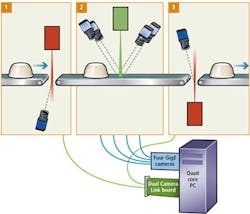
The system comprises three independent inspection stations designed around the Vision Development Module for LabVIEW software and PCIe hardware from National Instruments (NI), ensuring that each station could be modified as needed to address evolving inspection demands from the plate manufacturer (see Fig. 2).
While the first and the third stations of the system inspect the plate tops and bottoms for small imperfections, the second station captures a 3-D map of the plate so that its dimensions can be checked against a known reference template.
Because the dishes themselves are slightly translucent, in the first and third stages of the system, an EL137 high-intensity LED line light source from Advanced illumination illuminates the top and bottom of the plates.
Two Spyder S2-22-04K40 4-kpixel linescan cameras with a 9-kHz line rate from Teledyne DALSA—one at the first station and one at the third—capture the images of the white light transmitted through the plates. Image data are then transferred to a PC-based PCI Express (PCIe) 1430 dual Camera Link board from NI that is interfaced to a Dell Precision T3500 Xeon quad-core, 2.8-GHz PC with 4-Gbyte RAM where it is further processed using NI's IMAQ Vision software.
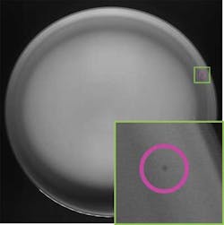
When a defect such as a bump is present on the plate, the thickness of that part of the plate is greater than the rest of the plate. Thus, as light travels through the plate and the image is captured by the cameras, the defect is highlighted as a dark spot (see Fig. 3).
The challenge of identifying such defects was compounded because they were not only small but also low in contrast in comparison to the rest of the plate. A further complication is that the low-contrast defects could be found in a part of the image that has large directional changes in intensity. As a result, it was impossible to filter these defects using a simple level threshold technique, because the defect itself would not necessarily represent the darkest area in the image.
Initially, Coleman Technologies considered capturing an image of a plate and making an image comparison with a "golden master" from which any discrepancies could be detected. But due to the large variations in image gradients between individual plates, the capturing of large 8-Mpixel images prior to analysis, and data needing to be processed in less than 0.5 s, the approach was rejected.
Instead, a pixel-by-pixel threshold algorithm was used on each image to effectively generate a "pseudo-golden master" image on a plate-by-plate basis. Before doing so, the size of the image itself was reduced to improve the computational performance of the PC system.
Because each of the particular defects to be identified only manifests itself around the rim of each plate, it is unnecessary to process and analyze the entire image. An image mask was initially considered as a means to localize the rim of the plate and to mask out other extraneous areas. However, this technique was rejected because large images would need to be processed and the computation time to do so would be exorbitant.
Unwrapping images
The alternative technique was to use IMAQ Unwrap, an NI LabVIEW Virtual Instrumentation (VI) module that is part of the Vision Development Module software suite. This approach was ultimately selected to eliminate as many unnecessary pixels from the image of the plate as possible.
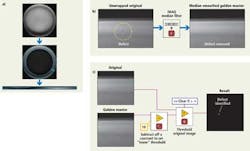
This VI is capable of extracting the image of the plate's annulus from an 8-Mpixel image while reducing the data to be processed down to 1.5 Mpixels (see Fig. 4a). This process also aligns all the image gradients and rim transitions in a vertical, rather than a radial direction—a move that also eased the computational burden.
With the 8-Mpixel image of the plate transformed into a more manageable 1.5-Mpixel strip, it is then possible to create a golden master from the image of each plate on a plate-by-plate basis by removing the defects from the captured image. To perform this task, a median smoothing kernel with a large pixel size in the horizontal (but not vertical) direction called IMAQ NthOrder is applied to the image (see Fig. 4b).
After the golden master is successfully created from the plate, it is then used as a standard with which the original image of the plate—with or without a potential defect—can be compared.
Before this is accomplished, a subtraction algorithm is applied to the image of the golden master to set a specific threshold level representing a defect. This image is then compared to the original image of the plate using the IMAQ Compare algorithm, which clears all the pixels in the original image if they are above the specific threshold, resulting in an image of the defect (see Fig. 4c).
The benefits of the pixel-by-pixel approach are multiple. First, the technique can identify defects within images with gradients, edges, speckle, and areas with large dynamic contrasts. Better yet, because each image that is captured is essentially checking against a golden master version of itself, the process is robust against variations between images and changing lighting conditions. The technique is also fast: It takes less than 100 ms to compute a 1.5-Mpixel image on a PC and the system can detect perimeter defects with less than 180-µm resolution.
Three-dimensional inspection
The first and the third stations of the image-processing system detect small defects on the plates from above and below, whereas the second station in the system inspects the dishes for geometric errors such as warps. To do so, the system uses a 3-D laser triangulation technique.
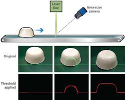
While a dish moves through the system down the conveyor belt, a BrightLine Pro 522-nm laser-line generator from LaserGlow with a 30° fan angle generates a structured laser line across the conveyor belt.
As the dish intercepts the beam, the beam traces the contours of the plate and an image of the contour is captured by four 1296 × 966-pixel, acA1300-30gm/gc ace area-scan cameras from Basler Vision Technologies set at 45° offset angles from vertical. The cameras, fitted with HF16HA-1B 2/3-in., 16-mm lenses from Fujinon, are operated with a reduced region of interest height to allow for acquisition rates greater than 100 frames/s.
Two cameras were deployed to address an issue: The high sides of some objects blocked a single camera's view of their trailing edges. But since each camera pair is only capable of imaging a 6-in. field of view (FOV), a second pair of cameras was added to image the widest plates with a 12-in. FOV.
Once captured, the image data from the cameras are transmitted to an NI PCIe quad-port GigE vision frame grabber capable of handling up to 100-Mbyte/s transfer rates per port, after which the data are processed in LabVIEW's IMAQ Vision software on the PC.
Each frame captured by the cameras provides a single cross-section of the dish. The various cross-sections that comprise the entire image are then stitched to form a complete 3-D image that can be compared to a true golden master image provided by the plate manufacturer.
By performing a thresholding operation on the cross-sectional images, it is possible to remove all but the profile outline of the plate created by the laser line source. The difference between the top and the bottom of this profile provides a measure of how far the laser line has deviated from a baseline (see Fig. 5).
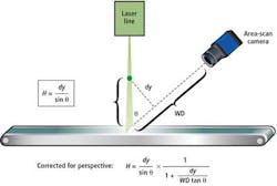
Because the height of the dish is a function of this deviation and the sine of the angle between the laser line source and its working distance from the intersecting line of the area-scan camera, the height of the dish at any given instance can be computed.
Using more complex geometry, it is also possible to correct for any distortions in perspective on the image caused by the fact that the higher the object is when it intersects the laser beam, the closer that intersection point is to the camera (see Fig. 6).
By capturing images of dishes moving down the conveyor line at 12 in./s and using area-scan cameras running at 100 frames/s, it is possible to achieve cross-sections every 3 mm with a 120-µm transverse resolution of the dish, and an approximate 100-µm height. Because the system is modular, more lasers or cameras can also be added to capture higher-resolution images of the dinnerware if needed.
Developed in three months and having been deployed for a year, the Coleman Technologies PQIS has already inspected more than 1 million dishes with an accuracy greater than 99%, finding major defects with a false positive rate near 0%.
Dan Milkie, PhD, is senior developer and Certified LabVIEW developer at Coleman Technologies (Newtown Square, PA, USA; www.colemantech.com).
Company Info
Advanced illumination
Rochester, VT, USA
http://advancedillumination.com
Basler Vision Technologies
Ahrensburg, Germany
www.baslerweb.com
Fujinon
Wayne, NJ, USA
www.fujifilmusa.com
LaserGlow
Toronto, ON, Canada
www.laserglow.com
National Instruments
Austin, TX, USA
www.ni.com
Teledyne DALSA
Waterloo, ON, Canada
www.teledynedalsa.com
