Machine-Vision Needs Change with Color Imaging: Part I


The portion of the electromagnetic spectrum visible to the human eye (VIS) responds to wavelengths from approximately 380–750 nm. The ultraviolet (UV) part of this spectrum lies below 380 nm, whereas the near-infrared (NIR) portion of the spectrum lies above 750 nm (see Fig. 1).
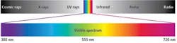
Imagers in red-green-blue (RGB) cameras deployed in machine-vision applications are able to sense wavelengths from 370 nm or a little lower depending upon the technology employed. Frequently, cameras have a range much higher than 750 nm, often above 1000 nm. In such cameras, the blue component of the light is absorbed at wavelengths between 380 and 500 nm, green between 500 and 600 nm, and red between 600 and 780 nm.
How are color filters used?
Color cameras obtain RGB channels of color in a variety of ways (see Fig. 2). The most common method uses a color filter array (CFA) or color filter mosaic (CFM), a mosaic of color filters placed over the photosites of an image sensor. For example, the Bayer filter gives information about the intensity of light in RGB wavelength regions. The raw image data captured by the image sensor are converted to a full-color image (with intensities of all three primary colors represented at each photosite) by a demosaicing algorithm, which is tailored for each type of color filter.
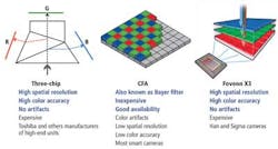
To obtain a higher spatial resolution, achieve higher accuracy, and capture images without demosaicing artifacts, a three-chip camera (available from manufacturers such as Toshiba) can be used. This type of design incorporates a micro-prism that separates the spectrum of white light into its RGB components, which are then separately imaged by three CCDs. Cameras based on this technology tend to be more expensive because three imagers are required.
A third type of technology for capturing RGB images has been developed at Foveon. Its X3 CMOS sensor leverages an array of photosites, each of which consists of three vertically stacked photodiodes organized in a two-dimensional grid. Each of the three stacked photodiodes responds to different wavelengths of light because different wavelengths penetrate silicon to different depths. The signals from the three photodiodes are then processed, resulting in data that provide the three additive primary colors: red, green, and blue.
Although cameras that employ the Bayer filter are the least expensive of the three options, they have low spatial resolution and low color accuracy. Color artifacts also occur in the interpolated images since only one color is captured at any one pixel location in the imager, and the values of the other two colors present at that pixel location must be interpolated.
Interpolating the green and blue values of the red pixel R5 shown in the center of Fig. 3, for example, can be accomplished in various ways. One is to perform a linear interpolation that produces a green or blue value by summing and averaging the green or blue values of the pixels surrounding the red pixel. Alternatively, a median interpolation can be performed in which the green or blue value of the pixel is replaced by the median of those in the neighborhood.
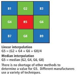
Aside from these techniques, many others are also used, each with its own degree of accuracy and computational demands. But whatever technique is used to interpolate the color values of the pixel, none can be 100% accurate. As such, system integrators should carefully evaluate the accuracy of the images generated to ensure that they will meet the demands of any specific application.
Lighting effects
Depending on the characteristics of the object to be inspected by a vision system, light from its surface will be reflected, scattered, transmitted, or absorbed. Objects may also emit light that they generate—rather than merely reflecting or transmitting light—because of their elevated temperature or as a result of certain chemical reactions.
In any vision inspection application, system integrators should assess how the object will modify the light and what effect this will have on the image captured by the camera. As a general rule, the less light reflected from an object and the more that is scattered, diffused, transmitted, or absorbed, the more light will be needed to illuminate it sufficiently.
Fluorescent, quartz-halogen, and LED lighting sources are widely used in machine-vision systems, while metal halide, xenon, and sodium lighting are used where very bright sources of light are required. Depending on the nature of the application, more than one type of lighting may be used.
Because most light sources do not produce 100% pure white light, any camera-based vision system must be accurately calibrated. For instance, if a halogen light illuminates a white object, the object may have a yellow hue, when in fact it should be white. Therefore, a digital camera needs to be calibrated to a reference white point from which all the other colors, such as red, green, and blue, can be calculated.
The type of light source used to illuminate an object greatly affects the color image that is captured by the camera, because each source of light has a unique spectral power-distribution curve. The curves of four different light sources—a fluorescent light, a white LED, a quartz-halogen light, and a metal halide light—provide a visual profile of the color characteristics of each light source, showing the radiant power emitted by the source at each wavelength or band of wavelengths over the visible region (see Fig. 4).
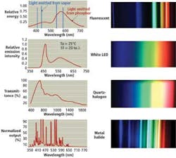
Because the intensity of light produced by each of the light sources varies uniquely according to frequency, the image of an object captured by a camera under different light sources will also vary. The differences in how color is rendered according to the type of lighting can be observed by illuminating an object by the four different light sources (see Fig. 5).
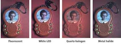
In this example, the white LED and the fluorescent light sources have both enabled the camera to render the colors in the image accurately. The image captured when the object was illuminated by a quartz-halogen light, however, is washed out, and the metal halide lighting has resulted in an image with a blue tint.
Stabilized light
The stability of the light sources used is also of paramount importance in a vision application. For fluorescent lighting, system integrators should ensure they choose high-frequency lighting in the 4000-to-20,000-Hz range to ensure that an object is illuminated consistently over time and eliminate any potential problems that might be caused by flickering at lower frequencies.
Light output from fluorescent lamps is also very sensitive to changes in the ambient temperature. A 20° temperature change from 20° to 40°C, for example, can result in the output from a lamp decreasing by as much as 20%. Also, any decrease or increase in the intensity of light from the lamp is not always linearly dependent on the decrease or increase in the temperature.
System integrators should also be aware that the luminosity of certain types of lighting—such as metal halide and quartz-halogen lights—will decay after several thousand hours of operation. Fortunately, many manufacturers provide graphs that illustrate how the luminosity of their products will decay over time, and system integrators can use these to determine how this change affects a system's performance.
Variations in temperature can change lighting performance and the sensitivity of the imager in the camera. As the temperature increases, the dark current of the imager will increase. If cameras are to be deployed in an environment where the temperature is expected to vary dramatically, system integrators should ensure that cameras can compensate for any variation in dark noise.
In Part II of this series, Glenn Archer will discuss the differences between the RGB and CIE Lab color models.