Engineers at Eberhard (Schlierbach, Germany; www.eberhard-ag.com), a builder of high-speed connector production equipment, have developed a machine vision system that simultaneously measures connector pin height and position without contact.
The new optical inspection system improves accuracy and reduces costs when compared to existing contact test methods, which typically require two different stations and complex, product-specific adapters, says Dr.-Ing. Bjoern Haller, head of development at Eberhard.
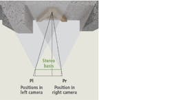
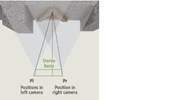
Figure 1: The 3D data calculated from the stereo images provides the coordinates of all object points in 3 dimensions – hence in x,y and z.
The application requires that the position of the pin tip (true position and pin height) be measured relative to a reference on the plastic body of the connector. In addition, the new system should be capable of measuring minimum pin dimensions down the current market standard of 0.4 x 0.5 mm. Manufacturing line speed requires inspection times in the range of four to ten seconds per connector, depending on the type of connector, Haller notes.
“Market-based tolerance ranges from 0.3-0.6 mm combined with finely structured pin-tip geometries require a minimum measuring system resolution of 15-20 μm,” Haller says. “And because pins typically reside within a pocket of the connector shell, angled illumination or image acquisition should be minimized to avoid unwanted shadows that can cause occlusions.”
Due to the combination of application requirements, Eberhard engineers compared various 3D cameras available based on the following criteria:
• High speed acquisition of at least 100 mm/s and fast calculation of theresult
• Minimal triangulation angle to avoid occlusions of pins by the connectorshell
• Pin position measurementstability
• 15-20 μm minimumresolution
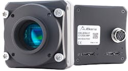
After considering their options, engineers specified 3DPIXA compact 15μm, 3D line scan cameras from Chromasens (Konstanz, Germany; www.chromasens.de) for several reasons.
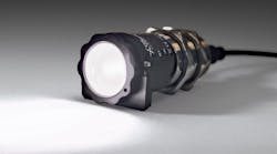
First, according to Haller, scanning and calculation speeds met or exceeded the required cycle time. Next, the line-scan technique delivers the resolution required for high accuracy measurements and allows optimized coaxial illumination that provides sufficient light into the deep pocket of the connector shell. Finally, the camera and the light are perpendicular to the object, minimizing occlusions.
Compared to a typical stereo vision system which would use two area scan cameras displaced horizontally from one another, the 3DPIXA uses a novel method of imaging 3D surfaces using a 7500 x 3 (RGB) line scan imager, combining stereo and line scan camera technology and enabling 2D color and 3D measurements. To capture 3D data, the camera system employs two lenses that are used to focus light onto both the right and left-hand sides of the line-scan imager.
Figure 2: The software models automatically measure more than 40 different parameters in real-time from size, count and concentration to color, grayscale and morphological characteristics such as circularity, elongation and fiber curl.
3D information is calculated by matching a set of points in one image with the same set of points in the second image – a task known as the correspondence problem. By comparing the two images, relative depth information can then be computed and represented in the form of a disparity map where objects that are closer to the stereo camera system will have a larger disparity than those that are further away (Figure 1).
Due to the high resolution required, the camera’s depth of focus is only 2.6 mm. Because the plastic housing reference is in a plane that’s 5-20mm from the plane of the pin tips, the pin tip and plastic reference cannot be focused on simultaneously in a single image. Consequently, the system acquires two images which are then related to each other. One image in the plane of the pin tip and the other image in the plane of the reference, with the distance between camera and connector adjusted to bring each plane into focus.
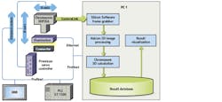
Figure 3: For fast calculation of the 3D data the software provided by Chromasens is running on graphic boards and is integrated in MVTec HALCON used for further analysis of the connector images.
Eberhard connector assembly lines typically use work-piece carriers. The plastic housing of the connector is placed in the carrier and the carrier transported within the unit by a walking beam mechanism.
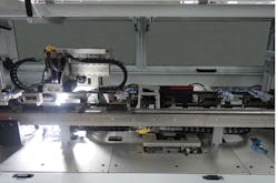
During inspection, the plastic housing of each connector seats in a work-piece carrier fixture ensuring correct position and angularity of the connector relative to the camera. The first image is recorded with focus on the reference plane. A linear servo motor from Jenny Science AG (Rain, Switzerland; www.jennyscience.de) moves the camera over the connector.
Continuous acquisition of the scanned image lines is synchronized with the feed by an external glass scale from Heidenhain (Traunreut, Germany; www.heidenhain.de) to ensure highest possible precision of the trigger signal. Depending on the connector and the achievable illumination, recording speeds of up to 280 mm/s have been achieved, notes Haller.
Raw image data is then transferred from the camera via Camera link interface to a frame grabber from Silicon Software (Mannheim, Germany; https://silicon.software) inside a PC. The Eberhard pin inspection software uses the HALCON library from MVTec (Munich, Germany; www.mvtec.com) to run the Chromasens 3D software and additional image processing tools.
After acquiring the first image, the linear servo motor returns the camera to its starting position, and camera height is adjusted to bring the pin tips into focus. Then the second image is acquired and the camera moves back to its starting position. The fixture is released and the walking beam mechanism transports the carrier to the next position.
“The 2D images show distinctive color gradients used to get a more stable result by processing the color channels individually and using the average of the resulting positions,” Haller explains. “For each connector type the image processing functions are parameterized accordingly to identify the position of pin tips and reference geometry (with subpixel accuracy) in the image. The wanted geometries are searched with algorithms programmed in HALCON. Output of this 2D image processing are the positions of the pin tips and reference points searched for in the left and right part of the stereo image.”
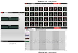
Figure 4: Screen shot showing the user interface for the end-user (operator).
Based on those pin-tip positions and reference positions identified in the two stereo images (A and B) the x-, y- and z-coordinates can be calculated using the coordinate system defined by the camera. This is done for the pin tips as well as for the reference positions in the particular image.
To ensure a precise calculation of the true position of the pins, both images have to be positioned accurately with reference to each other. That is, line 1 of the image acquired in the plane of the pins must exactly match line 1 of the image acuired from the reference plane. To achieve this, the previously mentioned Heidenhain glass scale is used. During operation, the reference mark of the glass scale triggers the image acquisition, while simultaneously providing highly accurate positioning.
To calculate the pin height, the exact distance of the camera height adjustment is measured by a high-accuracy digital contact sensor from Keyence (Osaka, Japan; www.keyence.com) which is fixed to the adjustment unit. With this accurate camera-height measurment, the difference between the heights of the two images in the z-direction is calculated to micron-level accuracy.
The calculated results for each connector are written into a database and visualized via a newly-developed human machine interface. The user can observe the running production on a live screen as well as evaluate historical data in point clouds, histograms or control charts.
