Transmission standards in machine vision
Following the announcement that Sony Europe’s Image Sensing Solutions division will launch its first machine vision camera module using the USB 3.0 standard, we asked the company to give an overview of the key transmission standards and their trade-offs.
Arnaud Destruels
Machine vision has played a huge role in improving both the quality of goods and their production speed, allowing for ever-better error detection and component placement. This is true in industries as diverse as manufacturing, pharmaceuticals, agriculture, intelligent transportation systems (ITS) and electronic board assembly. And not just for a subset of processes, but for a near unending set – from car inspection systems that minimize the risk of recalls to food sorting and even luxury-watch manufacturing, where previously only the reliance on master craftsmen was trusted.
As the technology has advanced, the emphasis has been placed not just on accuracy, but on cost and speed as well – without false positives / negatives being sent, and without slowing the production line.
Several factors come into play here: the sensor itself, how the camera module is optimized to get the most from the sensor, and how the machine vision system is designed. For example, how the lighting is controlled or the use of multiple cameras to capture several angles, or multi-capture and computational imaging and post-processing features, as well as how image data is transmitted.
In short, a great image is a result of multiple factors and a holistic design approach that delivers the most from the sensor. One key element of this design is how image data is transmitted from the camera, so that it isn’t lost or slowed.

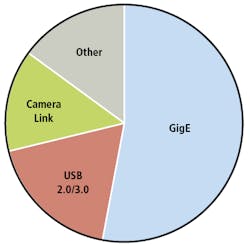
Figure 1: The three major standards - GigE, USB and Camera Link - account for 85% of the Machine Vision market by revenue. Other includes all standards with a smaller than 2% market share, including CoaXPress (4th largest by revenue) and FireWire (5th).
The key standards
For the EMEA region, predictions for 2019 suggest just three standards - GigE Vision, Camera Link and USB Vision (combined 2.0 and 3.0) - will be used in systems that make up 85% of the hardware market by revenue (Figure 1). This is broken down further below, showing the 12 most-commonly-used standards, including a breakdown for USB 2.0/3.0 (Figure 2).
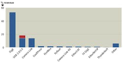
Figure 2: The next eight most-used standards account for less than 10% of the overall by revenue. USB 3.0’s relative market share is shown in red.
Balancing the trade-offs
One of the biggest trade-offs to be made in any project is bandwidth vs. distance, with cost and complexity also playing a significant role. As indicated in Figures 1 and 2, the three major transmission standards used for machine vision applications include GigE, Camera Link and USB. Figure 3a compares the trade-offs of bandwidth vs. complexity for the three major standards and Figure 3b compares the trade-offs of bandwidth vs. cable length, with standards ordered by cost, reducing from left to right.
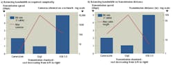
Figure 3: The trade-offs of bandwidth, transmission distance and complexity for the three major standards. Standards are ordered by cost, reducing from left to right.
More bandwidth allows for a greater number of features to be implemented, for example the Sony XCL-SG510 uses the Camera Link standard’s bandwidth to send 5.1 MPixel images at 154 fps and also implement features such as wide dynamic range, where multiple images are captured at varying exposure levels and a composite image created to bring out extra detail. Utilizing the new USB module (XCU-CG160) increases the available bandwidth significantly. The XCU-CG160 has been available in production quantities since April 2018.
This is, of course, not the complete picture with trade-offs also including cost, the number of cameras that can be placed on a network and the ability to improve transmission speeds by additional cables. For example, under the CoaXPress CXP-6 Quad standard, 4 cables can be used to deliver 25Gbps (4 * 6.25 Gbps). Camera Link can also use multiple cables to increase transmission speed, but the total speed depends on the configuration setup (base, medium, full, extended full) and it is not a simple doubling. Furthermore, other standards, such as IEEE1394b, enables multiple cables but for daisy chaining purposes only.
And on top of this is GigE Vision’s ability to use IEEE1588 to reduce overall system cost by eliminating the need for additional hardware - such as a GPS timing chip - when firing synchronization is needed between multiple cameras or system components.
Next generation standards
The choice of transmission standard also needs to work with existing infrastructure. We’ve shown the EMEA market share above, however, this varies significantly by region. In the Far East, Camera Link is very commonly used; whereas in Europe, GigE Vision has over 50% market share. However, we see that customers are pragmatic and would consider a switch to Camera Link, where the application allows, due to the superior frame rate it supports.
Added to this issue in choosing the right standard is the rise of next generation transmission standards - such as 10 GigE and Camera Link HS, both of which allow transmission speeds up to 10 Gbps (depending on configuration) over longer distances, with 10 GigE allowing up to 100m.
Not all of these new standards are backwards compatible, though, and this may ultimately affect adoption. Standards like 10 GigE, which is backwards compatible, allows it to be integrated seamlessly with existing infrastructure and conversely, Camera Link HS is not simply an evolution of the 2.0 standard and this may mean its adoption takes longer.
Making the system work cohesively
Be it for agriculture, ITS functions, factory robots, indeed for a vast (and growing) number of applications, the ability for multiple cameras – and the entire system – to communicate in order to take more informative images is vital.
For example, an inspection robot that picks bad fruit from a conveyor (with produce coming down constantly, often covered in dirt) needs images from multiple cameras to interpret exactly which meet supermarket standards, which are acceptable albeit imperfect, which can go to juice, and which are damaged, infected or moldy.
To manage this, with few false positives and even fewer false negatives, it needs multiple cameras – with color, near-infrared and even polarized and/or hyperspectral sensors – to distinguish between a normal mark, a bruise, an infection and even a hidden object under the skin. The ability for cameras to fire at precisely the same time and capture exactly the same image is therefore vital.
With a standard camera, there is an internal clock. These clock speeds are arbitrary and unique to each camera and there is no link between devices. As each device on a network has its own clock; you cannot program a module to fire at a specific time. Traditionally the way to manage this is to use hardware triggering, based on technologies such as GPS, which is accurate to the nanosecond but adds significant cost and also creates a single point of failure in the system.
The alternative is to use software, using the precision timing protocol IEEE1588, which can be implemented with the GigE v2.0 communication standard (see “IEEE1588 simplifies camera synchronization,” Vision Systems Design, April 2017; http://bit.ly/VSD-1588). This dynamically assigns a master clock (allowing for component failure) and, at regular intervals, synchronizes all components in the system to the same clock. Using this protocol, it is possible to get the precision to microsecond accuracy. While less precise than GPS chip’s nanosecond synchronization, it is more than accurate enough for virtually all machine vision applications (Figure 4a and Figure 4b).
Furthermore, the protocol is being used to link not just cameras, but the rest of the system - be it robots, a camera’s lens or the lighting. Individual components can exchange parameters via Ethernet and be triggered over Ethernet, which means it’s possible to accurately synchronize, for example, the light pulses and the camera ring and adjust quickly on the fly.

Figure 4: Resynchronizing a fast and slow camera to the master using the precision time protocol via IEEE1588.
In machine vision systems, cameras were traditionally capable of acting solely as the IEEE1588 slave device, with a dedicated item of hardware needed as master, plus a backup included in case of failure. This again added cost. However, in 2016, Sony launched the first machine vision camera capable of being the master.
2017’s Sony XCG-CG510 and XCG-CG240 take this concept further to combine an acquisition scheduler as well as software-trigger, GPO-control and user set load action command types. This enables Sony’s GS CMOS machine vision cameras to realize a precise, pre-scheduled, image acquisition synchronization in real-world environments that can provide a level of precision several hundred times more precise than competing modules.
Summary
Machine vision has played an inarguable role in improving both the quality of goods and their production speed, allowing for ever-better error detection and component placement. Several factors affect the ability for a camera module to capture an image accurately and a holistic design approach is essential if you are to get the best possible image from a sensor. The camera module design must be optimized for the sensor, as should the complete system, with transmission standard chosen not just for the size and speed of image transmission, but for the features they enable - be it the synchronization of lighting, robotics and camera triggering, or for the bandwidth to allow wide dynamic range.
Related stories:
Finding the optimal hardware for deep learning inference in machine vision
OPC Machine Vision part one officially adopted
Understanding unique machine vision illumination methods
Share your vision-related news by contacting Dennis Scimeca, Associate Editor, Vision Systems Design
SUBSCRIBE TO OUR NEWSLETTERS