How to handle optical design challenges in 3D imaging
Jeremy Govier
Measuring the depth of an object in 3D metrology presents a unique set of challenges, as a different suite of tools and different optical solutions than those used for measuring length and width are necessary.
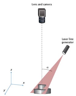
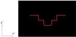
There are several methods for non-contact 3D metrology that all use optics, such as time of flight, stereo vision, structured light projection, and laser triangulation. Laser triangulation uses a laser line projected onto an object at an oblique angle to the object’s depth, referred to as the z-axis. A camera observes the object with the camera’s optical axis parallel to the z-axis, and changes in depth in the object are translated into changes in y’ on the camera sensor (Figures 1 and 2).
The advantage of laser triangulation over similar 3D metrology techniques is its higher resolution along the depth of the object.1 The range of depth that is measurable using laser triangulation is smaller than that of most of the other 3D metrology technologies, but the achievable resolution is also higher.
Measurable range of depth and the resolution of the depth measurements can be adjusted by changing the triangulation angle (α). The smaller the triangulation angle, the greater the depth range. However, smaller triangulation angles also correspond to coarser, or lower, resolution. Likewise, larger angles correspond with finer, or higher, resolution but more limited range of depth.2 Therefore, by adjusting the triangulation angle, one can achieve the right balance of resolution and depth range. The product of resolution and depth range can only be increased by increasing both the number of pixels in y’ and the resolution of the lens system.
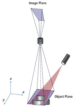
To ensure that the entire depth of the object is in focus, it is common to tilt the image plane of the camera. Using the Scheimpflug condition, tilting the image sensor tilts the plane of best focus for the object relative to the optical axis (z-axis).3 This tilt of the object plane is adjusted so the object plane is parallel to the axis of the laser, allowing the entire laser line to be in focus as it is projected over the varied depth of the object (Figure 4). This Scheimpflug condition adds unique challenges for the optical design of laser triangulation systems, as they affect many of the other parameters and design considerations.
Along with aperture, it is important to consider relative illumination in laser triangulation systems. To deal with a relative illumination problem, the lens may need to further increase throughput because the lowest relative illumination points in the field drive the minimum throughput required in the lens. Due to the tilted image plane in the Scheimpflug condition, the relative illumination of a lens is generally more critical for laser triangulation applications than for that of a typical machine vision application. The angle at which the chief ray, or central ray, strikes the detector will affect the intensity of that point. This radiometric effect is especially detrimental when using sensors containing microlenses. If the lens is not telecentric in image space, the chief ray angle at the center of the field will be different from those at the corners of the field.
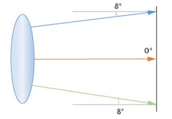
For example, a typical machine vision lens will have a 0° chief ray angle in the center of the image because the chief ray is perpendicular to the sensor. However, the chief ray angle can vary up to 8° at the corners of the field. The top and bottom corners of the field can both have a chief ray angle of 8°, but the angle will be in different directions away from the center, resulting in a maximum variation across the field of 8° (Figure 5). However, if the sensor is tilted by an additional 8°, the chief ray angle at the top of the field is now 16° while the chief ray angle at the bottom is now 0°, leading to 16° of variation (Figure 6). This can cause significant non-uniformities across the image. Designers should consider reducing the chief ray angle and making their solutions more image-space telecentric to reduce these non-uniformities.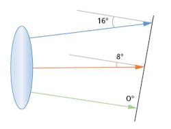

The asymmetry of the system should be considered early in the design process. Systems in which the lens is used with a tilted image plane will not be rotationally symmetric, and this needs to be considered in the optimization. First, the image plane should be modeled as a rectangle, not a single radial axis. The common design practice for rotationally-symmetric systems is to only model the y-axis to reduce the number of field points that need to be calculated during optimization, but with tilted image planes, the field points will not behave the same at each corner of the sensor. With the keystone distortion, either the image size or object size will not be rectangular if the other is rectangular. Treating the image plane as a rectangle will also allow for evaluation of the resolution in z- and x-axes separately, as one may have higher requirements than the other in the application.
Starting with a rotationally-symmetric system in the initial optimization can speed up the design process, but before long, the tilted image plane should be included to better optimize for the unique aberrations that will occur due to the Scheimpflug condition. Because the application requires the lenses to run fast with large apertures, reducing spherical aberration in the initial untilted design will help improve performance in the final tilted design.
But this alone is not enough, as the residual spherical aberration can transform into more complicated higher order aberrations when tilted. Optimizing around the actual configuration results in a better performing final design.
One important consideration with tilted image planes is how the image sensor cover glass affects performance. Image sensors typically have a thin window attached to the front, so if the sensor is mounted tilted to the optical axis, this window will also be tilted. An untilted window adds spherical aberration to the system as a function of the working f/#, index of refraction of the window, and the window thickness.
In an untilted design, this can be compensated by the presence of the opposite amount of spherical aberration. On the other hand, a tilted window adds astigmatism as opposed to spherical aberration, and this cannot be compensated for in the design without adding further asymmetries. Therefore, there will be a baseline of image degradation that is purely a function of the tilt angle, the window geometry and material, and the aperture of the lens. The optical designer will not be able to reduce the aberration below that baseline. This can reduce the amount of design complexity since there is a limit to what is truly achievable in the design. This limit may also cause system engineers to consider removing or tilting the window.
There are costs and difficulties associated with either of these options, but they may be necessary to achieve the maximum performance of the system. When modeling the tilts in the system, starting with the Scheimpflug equation (below) will determine the image tilt based on the object tilt and the focal length of the lens (Figure 8).3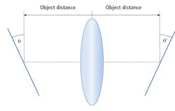

However, the designer should be aware that this equation is a thin lens approximation, where the front and back principal planes are at the same location. The design may have a separation between the principal plane locations that will throw off this approximation. While the Scheimpflug equation will get close, it is always best to allow the tilt of the image plane to be a variable so that it can be optimized to maximize performance.
The unique geometry of a laser triangulation system for 3D metrology applications presents challenges, but with special care from the optical designer, the imaging lens can find the best balance of high resolution and large aperture, while staying within the constraints of the application.
References
1. Franca, J.g.d.m., et al. “A 3D Scanning System Based on Laser Triangulation and Variable Field of View.” IEEE International Conference on Image Processing 2005, Sept. 2005, doi:10.1109/icip.2005.1529778.
2. “Applications: Measuring and Process Control in 3D Using Laser Lines, Laser Spots and Laser Patterns.” Schäfter Kirchhoff, 2013.
3. Smith, Warren J. “Chapter 2.14.” Modern Optical Engineering: the Design of Optical Systems. McGraw Hill, 2008.
4. Dorsch, Rainer G., et al. “Laser Triangulation: Fundamental Uncertainty in Distance Measurement.” Applied Optics, vol. 33, no. 7, 1994, pp. 1306–1314., doi:10.1364/ao.33.001306.