Boosting productivity in medical device inspection and labeling
Employing a rotary indexing table, an automated system checks and labels electrophoresis units at speeds of up to 22 parts per minute.
Jeff McKenney
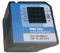
Electrophoresis is used in laboratories to separate macromolecules based on size. Useful in DNA, RNA, protein and cell analysis, electrophoresis applies a negative charge so proteins move towards a positive charge. To reduce the separation time, while reducing the amount of samples and reagents required, microfluidic cartridges consisting of a number of sample wells interconnected by micro-channels fabricated in glass are commonly used (Figure 1).
Once the micro-channels are filled with a sieving polymer and fluorescence dye, the "chip" becomes an integrated electrical circuit. Electrodes in each well of the circuit are then powered to drive charged biomolecules such as DNA or RNA through a sieving polymer matrix in the circuit, separating them by size. These are then detected by laser-induced fluorescence and data is translated into gel-like images and electropherograms to determine, for example, types of genes that are based on the length of specific DNA fragments.
Perfectly formed
After these so-called "laboratories-on-a chip" are manufactured, it is imperative that the wells or chimneys are perfectly formed and mounted correctly. If this is the case, then the devices can be labeled and shipped to the customer.
In the past, one manufacturer used a machine that required a worker to take each assembly from a stack and place it on a conveyor belt, which fed the assemblies into a labeling machine. After being labeled, assemblies exited the machine, were manually restacked and a final inspection performed.
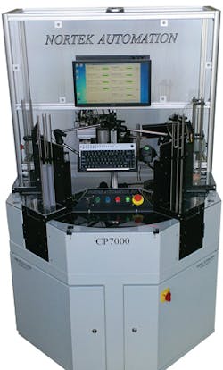
To increase the throughput and reduce the manpower required, Nortek Automation (Huntington Beach, CA; USA;www.nortekautomation.com) was tasked with developing a machine that would automatically feed assemblies from the stack, inspect them, label them and re-stack the finished product (Figure 2).
To accommodate both 1.75 x 1.75mm and 1.75 x 0.75mm devices, the Nortek CP7000 accommodates two magazine racks each of which can hold 75 devices (Figure 2, left). While only one type of part is fed, inspected, labeled and re-stacked during a batch run, the design allows a rapid changeover of parts to be made.
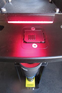
After the devices are stacked, a pneumatic gripper releases each part onto a rotary indexing table and into a custom-designed nest that can hold different part sizes (see "Custom-built nest accommodates different part sizes," p. 16 this issue). Moving clockwise, the part is then indexed to a vision system station that checks whether the wells are properly aligned in the carrier (Figure 3).
To accomplish this, the part is first illuminated with a QL Series QBL red LED backlight from CCS America (Burlington, MA, USA;www.ccsamerica.com). Light from this backlight travels through the nine wells of the part and is imaged by an In-Sight 7200 camera from Cognex (Natick, MA, USA; www.cognex.com) that is fitted with a TC-13048 telecentric lens from Opto Engineering (Mantova, Italy; www.opto-engineering.com). Since known good parts will produce an image of perfectly formed circles at known locations, Nortek Automation chose Cognex's PatMax software, running on the In-Sight 7200 to compare captured images with a known good template.
Chips and scratches
To check for the presence of defects such as chips, scratches or nicks on the part's integrated electrical circuit, the part is then illuminated by a QL QRL red LED ring light from CCS America that is mounted on the front of the telecentric lens.
While captured images of the circuit can be compared with known good templates using PatMax, Cognex In-Sight software also allows the manufacturer to tailor the system to inspect other types of defects, if so required.
Fifteen defects need to be detected at this stage including chipping on the edge of the chip and scratches on the clear plastic lenses on its surface. When a defect is present, it glows under illumination from the front light. The CP7000 uses Cognex's PatMax to teach known-good features of chips, and to detect and reject chips whose glow pattern does not match those features.
Results of these inspections are then transferred over Ethernet to an Intel Pentium-class CPU running the Windows 7 operating system. Should a part fail both of these inspections, it is indexed around the rotary table without labeling. If a part passes the inspection, it is then indexed to a labeling station. Here, labels from a modified 600dpi thermal printer are first printed and transported through a peel plate onto a stage plate. A custom-built pneumatically controlled X-Z pick-and-place mechanism then transfers the labels from the stage plate and onto the part. This label containing the lot number, expiration date and 1D or 2D bar-code must then be inspected for proper placement, OCR and bar-code readability.
To accomplish this, the table is again indexed to an imaging station that consists of a Cognex In-Sight 7200 camera. With integrated red LED illumination, the camera verifies label position accuracy and uses Cognex OCR and 1D/2D barcode tools to read the product lot number and expiration date and verify the label is correct. Once again, these results are transferred over Ethernet to the system's host PC.
Parts that fail the well/chip inspection or label inspection stations are rejected prior to reaching the offload station. Only parts that pass both vision stations are labeled and indexed to the offload station. Here, the units are lifted pneumatically and stacked into the magazine at the offload station (seen on the right of Figure 2). Only known-good, inspected, labeled, and verified parts are re-stacked.
All rejects are automatically removed from the nest before the offload station. This eliminates the possibility of failed parts mixed with deliverable parts.
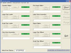
To allow the operator to monitor the program functions of the machine, the host PC that is used to interface with both vision systems, the indexing mechanism and pneumatic controls, is used to display the interface to all the main system functions (Figure 4).
Written in Visual Basic, this interface allows the user to start, stop or pause the machine and set the inspection and print functions.
A second I/O diagnostics window allows the operator to monitor the status of the mechanical actuators and vacuum functionality.
By automating chip handling, the Nortek CP7000 delivers seventy percent higher throughput while reducing operator labor from three people to two. It has eliminated the labor of manual inspection while providing more consistent quality results.
Costing approximately $150,000, the system is now in use at a major vendor of bioanalyzer modules. A video of the system in operation can be seen atbit.ly/1QjrnC1.
Jeff McKenney, Vice President of Engineering, Nortek Automation (Huntington Beach, CA; USA www.nortekautomation.com)
Custom-built nest accommodates different part sizes
In developing the nest to accommodate two different part sizes, it was important that the nest provide an unobstructed view of the glass chip on the underside of each device. Although there are two different size parts (approximately 1.75 x 1.75 and 1.75 x 1.125in) the parts contain the same size glass chip.
On the larger part, the glass chip is offset to the right while on the smaller part it is centered in the nest. There is a large cutout in the nest allowing a clear field of view for the camera and lighting mounted below. The cutout is nominally oversized to allow a significant amount of light from the ring light situated below to illuminate the part. This allows the glass chip to be inspected for any scratches, chips, bubbles and other defects. The cutout also gives the vision system a clear view of each well (chimney) to examine the chip placement.
While the large chip is mostly square and was easily justified in X and Y, the small part has rounded features on the nose and tail making fixturing more difficult. This challenge was overcome by introducing a small tab that matched the radius of the part tail.
The locating features for each part in the nest are characterized by a slight vertical taper leading into a straight-walled pocket. This style of nest is required to simplify the loading process by guiding the part into the final, mechanically-registered position.
Horizontal slots spanning each nest are required for clearance for the offload mechanism. The lifting fingers at each offload station will come up through the slots, making contact with the part and eventually pushing the part through the spring catch of the offload station.
Companies mentioned
CCS America
Burlington, MA, USA
www.ccsamerica.com
Cognex
Natick, MA, USA
www.cognex.com
Nortek Automation
Huntington Beach, CA, USA
www.nortekautomation.com
Opto Engineering
Mantova, Italy
www.opto-engineering.com
